Light scanning apparatus

Active Publication Date: 2016-12-01
CANON KK
View PDF3 Cites 25 Cited by
  • Summary
  • Abstract
  • Description
  • Claims
  • Application Information

AI Technical Summary

Benefits of technology

[0008]The present invention has been made in view of the circumstances as described above, and it is an object of the present invention

Problems solved by technology

However, the increase in rotational speed of the drive motor causes a centrifugal force to act on the rotary polygon mirror through rotation of the rotary polygon mirror, with the result that vibration energy synchronized with the rotation period of the drive motor is propagated from the rotary polygon mirror over the entire optical box via the drive motor.
This causes vibration of the optical members such as lenses and mirrors supported in the optical box, leading to beam vibration synchronized with the rotation period of the drive motor in the light spots formed on the photosensitive member, and eventually causing pixel deviation, density unevenness, and other image deterioration.
Further, there has been a problem in that the vibration energy propagated over the entire optical box vibrates the entire light scanning apparatus at various amplitudes ranging from small to large ampl

Method used


Image

  • Light scanning apparatus
  • Light scanning apparatus
  • Light scanning apparatus

Examples


first embodiment

[0067][Overview of Image Forming Apparatus]

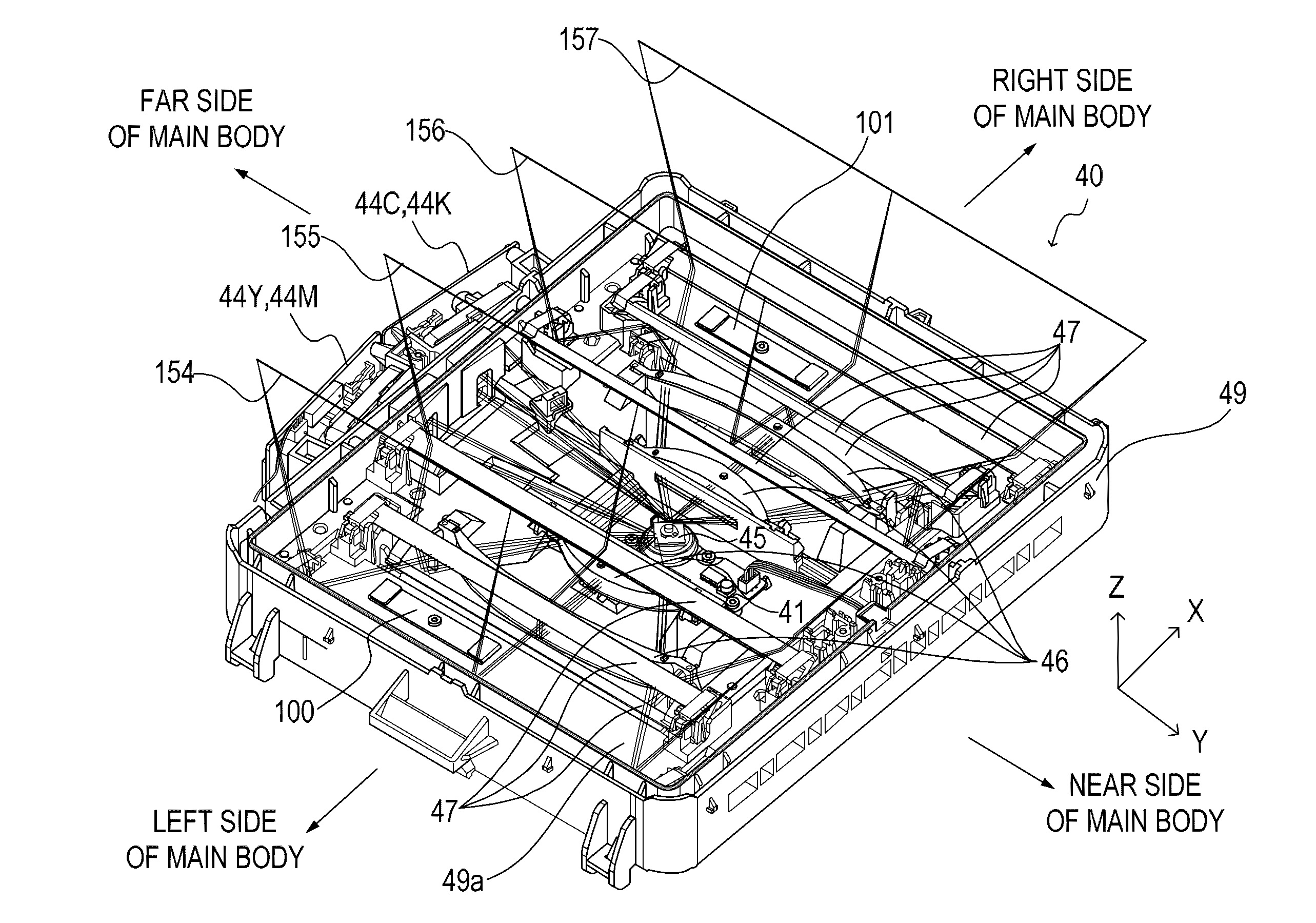
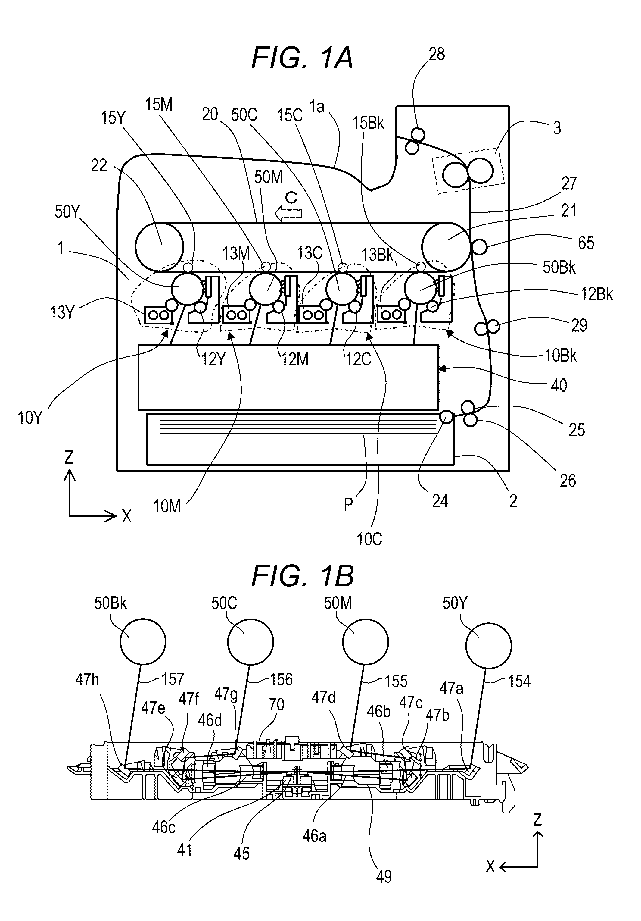
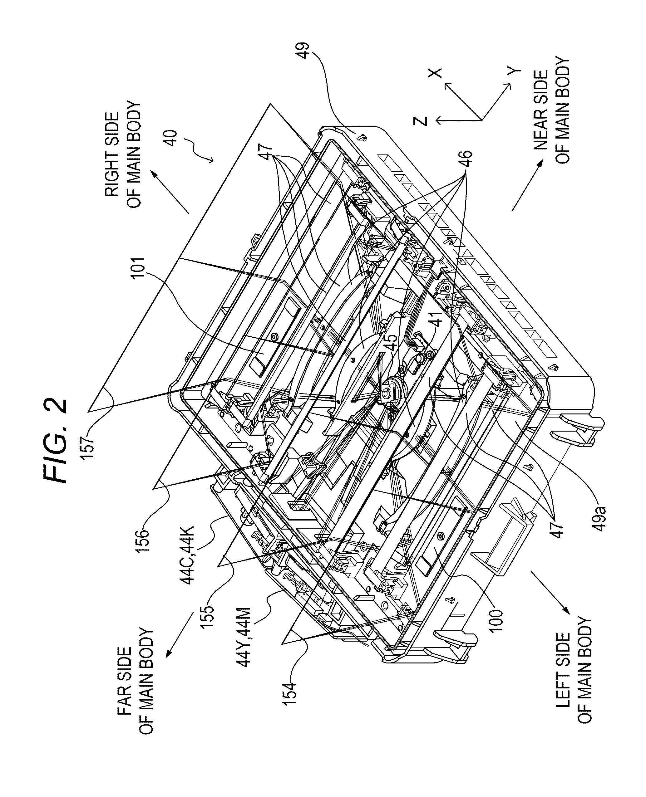
[0068]The structure of an image forming apparatus according to a first embodiment of the present invention is described below. FIG. 1A is a schematic structure view for illustrating the overall structure of a tandem color laser beam printer according to this embodiment. The laser beam printer (hereinafter simply referred to as “printer”) includes four image-forming engines 10Y, 10M, 10C, and 10Bk (indicated by chain lines) configured to form toner images of yellow (Y), magenta (M), cyan (C), and black (Bk), respectively. Further, the printer includes an intermediate transfer belt 20 to which the toner images are transferred from the respective image-forming engines 10Y, 10M, 10C, and 10Bk, and is configured to form a color image through transfer of the toner images, which are transferred to the intermediate transfer belt 20, to a recording sheet P serving as a recording medium. Symbols Y, M, C, and Bk representing the respective colors are ...

second embodiment

[0131]In the second embodiment, the structure of the dynamic vibration absorber, which is capable of securing a large clearance between the dynamic vibration absorber and a scanning beam passing above the dynamic vibration absorber in the Z-axis direction to reduce the risk that the dynamic vibration absorber may interfere with the scanning beam, is described. The functions of a printer serving as an image forming apparatus and the light scanning apparatus 40 are the same as those in the first embodiment, and hence their description is omitted below and differences from the first embodiment are only described.

[0132][Structure of Dynamic Vibration Absorber]

[0133]FIG. 16 is a perspective view for illustrating, on an enlarged scale, a peripheral portion of a CK-side dynamic vibration absorber 146 (referred to also as “dynamic vibration absorber 146”) installed in the optical box 49 according to this embodiment. A position where the CK-side dynamic vibration absorber 146 is installed in...

third embodiment

[0139]According to the first and second embodiments, the dynamic vibration absorbers are installed inside the optical box in which the optical members are supported. According to a third embodiment of the present invention, there is described the structure in a case where dynamic vibration absorbers are installed on a back surface of the optical box on which no optical member is disposed. The functions of a printer serving as an image forming apparatus and the light scanning apparatus 40 are the same as those in the first embodiment, and hence their description is omitted below and differences from the first embodiment are only described.

[0140][Structure of Dynamic Vibration Absorber]

[0141]FIG. 18 is a perspective view of the optical box 49 according to this embodiment when viewed from the back surface side. As illustrated in FIG. 18, dynamic vibration absorbers are fixed to the back surface opposite to the bottom surface of the bottom portion 49a of the optical box 49 to which the ...


PUM


Abstract

A light scanning apparatus, including: a light source; a rotary polygon mirror configured to deflect a light beam emitted from the light source; a plurality of optical members configured to guide the light beam, which is deflected by the rotary polygon mirror, to a photosensitive member; a drive motor configured to rotate the rotary polygon mirror; an optical box to which the light source is attached, the optical box containing the rotary polygon mirror, the drive motor, and the optical members; and a dynamic vibration absorber mounted inside the optical box and configured to be vibrated by vibrations of the optical box, wherein the plurality of optical members are supported on a bottom portion of the optical box, and the dynamic vibration absorber is disposed on the bottom portion of the optical box at a position between at least two adjacent optical members among the plurality of optical members.

Description

BACKGROUND OF THE INVENTIONField of the Invention[0001]The present invention relates to a light scanning apparatus. In particular, the present invention relates to a light scanning apparatus to be provided in an electrophotographic image forming apparatus such as a digital copying machine, a laser beam printer, and a facsimile apparatus.Description of the Related Art[0002]Hitherto, in a light scanning apparatus to be used in an electrophotographic image forming apparatus, a light beam emitted from a light source is deflected by a rotary polygon mirror and condensed by a scanning imaging optical system toward a photosensitive member to form light spots on the photosensitive member. The light scanning apparatus is configured to scan the photosensitive member with the light spots to form a latent image on the photosensitive member. The formed latent image is developed with a developer (toner) into a toner image. The toner image is transferred to a recording sheet and fixed on the recor...

Claims


Application Information

Patent Timeline
IPC IPC(8): B41J2/47G03G15/04
CPCG03G15/04036B41J2/471G03G15/0409G03G15/043
Inventor ISHIDATE, TAKEHIRO
Owner CANON KK
Why Eureka
Try Eureka