Method of evaluation wind flow based on conservation of momentum and variation in terrain

a technology of momentum conservation and wind flow, applied in the direction of fluid speed measurement, instrumentation, design optimisation/simulation, etc., can solve the problems of not being representative of the true potential of the wind farm, not being representative of long-term climatic conditions, and not being able to observe the wind flow across a given area

Active Publication Date: 2016-12-01
ONE ENERGY ENTERPRISES INC
View PDF16 Cites 22 Cited by
  • Summary
  • Abstract
  • Description
  • Claims
  • Application Information

AI Technical Summary

Problems solved by technology

If the wind flow model is flawed or biased, then all subsequent calculations will inherit those errors and the assessment will not be representative of the wind farm's true potential.
Often, the period of record for on-site measurements is not representative of long-term climatic conditions.
Wind flow across a given area is not typically consistent from point to point.
In flatter sites, while the variation in measurements between met towers is smaller, it has been shown that terrain effects are still significant in affecting the spatial wind flow.
In general, linear models are viewed as simple and quick to produce estimates but are known to produce estimates with significant error, particularly in complex terrain.
CFD models are typically very complex and require extensive training, resources, and knowledge to use to accurately predict wind flow across a site.
In general, there have not been consistent results showing the superiority of either linear or CFD models.
However, some studies showed the CFD model producing a lower error than WAsP.
However, this is not always the case, and the error in CFD models can be substantial.

Method used


Image

  • Method of evaluation wind flow based on conservation of momentum and variation in terrain
  • Method of evaluation wind flow based on conservation of momentum and variation in terrain
  • Method of evaluation wind flow based on conservation of momentum and variation in terrain

Examples


Embodiment Construction

[0032]The invention disclosed herein describes a new model to predict the spatial variation of wind flow at a site. The invention uses derivations of Newton's second law, which states that the change in momentum of a moving fluid is equal to the net force acting on that fluid. The Navier-Stokes equation is used to represent Newton's second law, and is described on pages 190-191 of Fluid Mechanics with Engineering Applications, 9th Edition, 1997 by Joseph B. Franzini and John E. Finnermore, and incorporated herein by reference. Further detail on the derivations of the equations behind the present invention from Navier-Stokes can be found in Continuum Wind Flow Model: Introduction to Model Theory and Case Study Review by Elizabeth Walls, incorporated herein by reference. In the following discussion, the following variables are defined:

[0033]UW: Upwind

[0034]DW: Downwind

[0035]θ: Slope of terrain.

[0036]WS: Wind speed.

[0037]WD: Wind direction sector

[0038]Xi=the ith easting coordinate in t...


PUM


Abstract

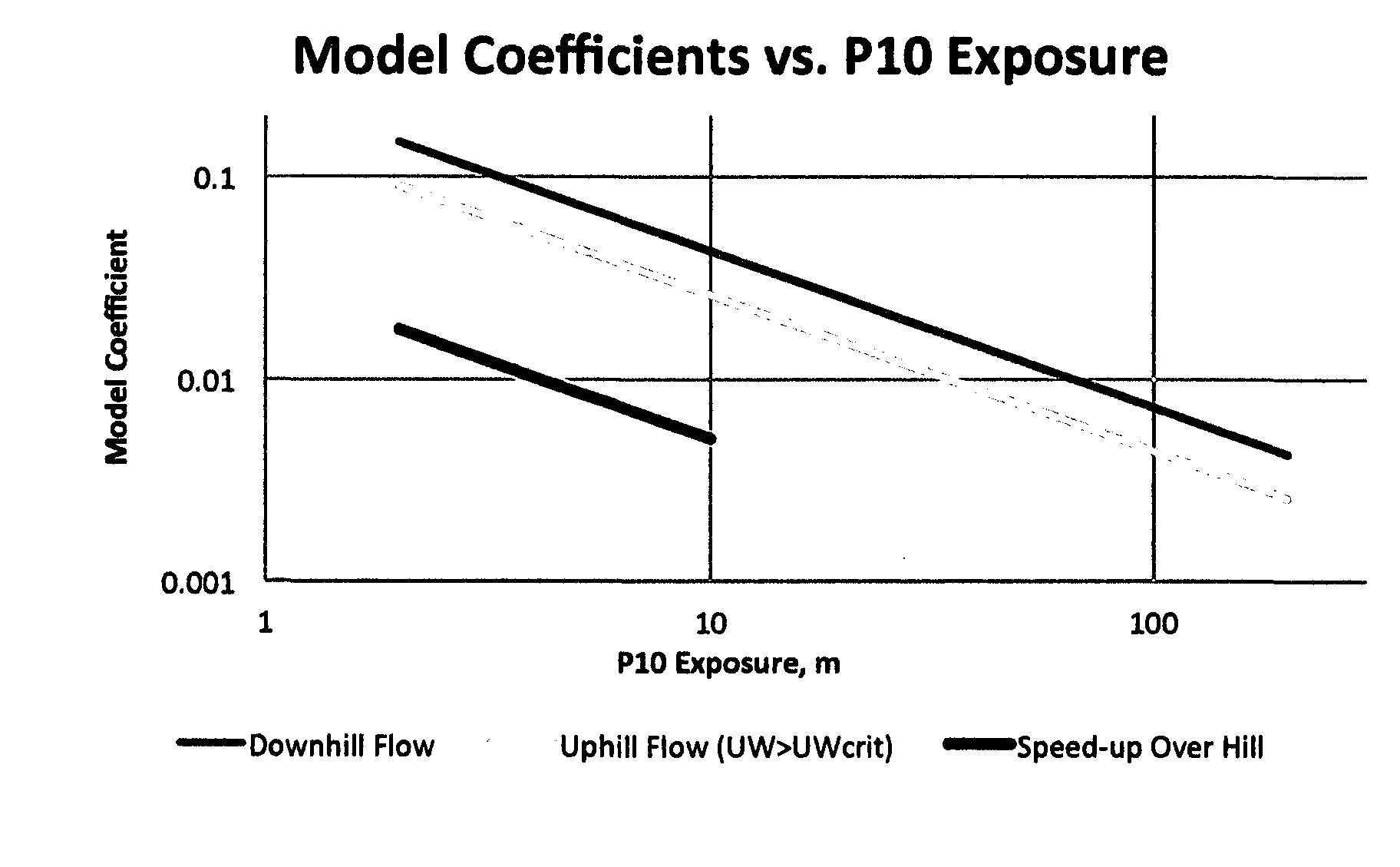
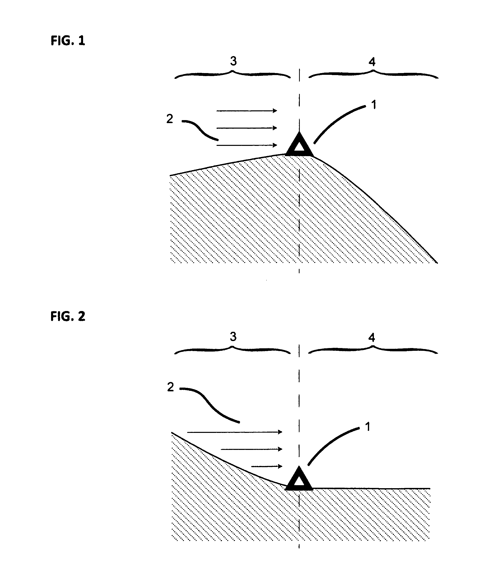
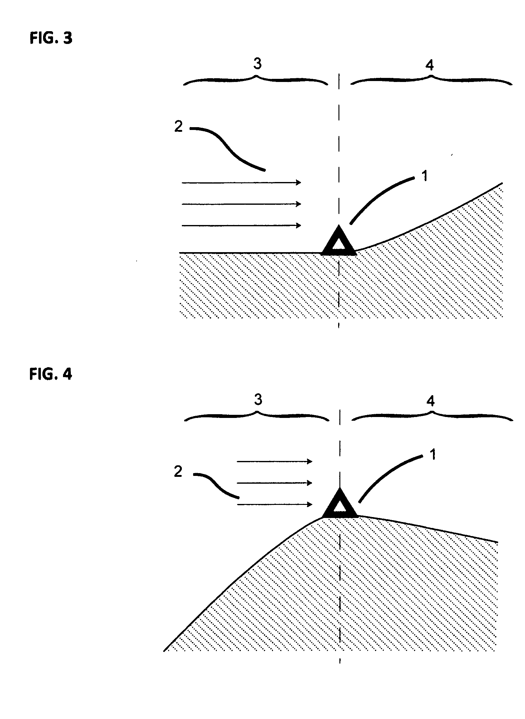
A method of modeling the spatial variation in wind resource at a prospective wind farm site. The method involves a simplified analysis of the Navier-Stokes equation and utilizes data from all of the met sites simultaneously to develop site-calibrated models. The model coefficients, mUW and mDW, describe the sensitivity of the wind speed to changes in the upwind and downwind terrain exposure and are defined for downhill and uphill flow. The coefficients are a function of terrain complexity and, since terrain complexity can change across an area, the estimates are performed in a stepwise fashion where a path of nodes with a gradual change in complexity is found between each pair of sites. Also, coefficients are defined for each wind direction sector and estimates are performed on a sectorwise basis. The site-calibrated models are created by cross-predicting between each pair of met sites and, through a self-learning technique, the model coefficients that yield the minimum met cross-prediction error are found.

Description

FIELD OF THE INVENTION[0001]The present invention relates to a method to estimate and predict the spatial variation in wind energy resource at a prospective wind energy site. In particular, the invention utilizes the theory of conservation of momentum (Navier-Stokes) and wind data measured at two or more meteorological (met) towers to develop a wind flow model based on how the upwind and downwind terrain changes between the respective met towers and on whether the wind flow is uphill, downhill, or over a hill.BACKGROUND OF THE INVENTION[0002]In wind energy resource assessment, it is the primary goal to estimate the annual net energy that could be produced from a potential wind farm. This assessment includes several elements such as a wake loss model, long-term climatic adjustments, and a wind flow model. The wind flow model is the foundation of the wind resource assessment as it is used to estimate the free-stream (un-waked) wind speed distribution across the project area, which is ...

Claims


Application Information

Patent Timeline
Patent Type & Authority Applications(United States)
IPC IPC(8): G06F17/50G06F17/10G01P5/00
CPCG06F17/5009G06F17/10G01P5/001G01P5/00G01P13/045G06F30/20
Inventor WALLS, ELIZABETH
Owner ONE ENERGY ENTERPRISES INC
Why Eureka
Try Eureka