Ion beam etching apparatus and ion beam generator

a technology of ion beam generator and ion beam etching, which is applied in the direction of electrical equipment, electric discharge tubes, basic electric elements, etc., can solve the problems of widening and narrowing of the gap between the grids, so as to reduce the gap differences between the grids and the misalignment of the grid holes between the substrate side and the plasma side. , the effect of reducing the misalignment of th

Inactive Publication Date: 2016-12-01
CANON ANELVA CORP
View PDF8 Cites 32 Cited by
  • Summary
  • Abstract
  • Description
  • Claims
  • Application Information

AI Technical Summary

Benefits of technology

[0012]According to the present invention, the positional misalignments of grid holes between the substrate side a...

Problems solved by technology

The deflections on the grids may cause positional misalignments of grid holes between the substrate side and the plasma side.
Moreover, the deflections on the grids may cause gap differences among the grids, so that the gap among t...

Method used


Image

  • Ion beam etching apparatus and ion beam generator
  • Ion beam etching apparatus and ion beam generator
  • Ion beam etching apparatus and ion beam generator

Examples


first embodiment

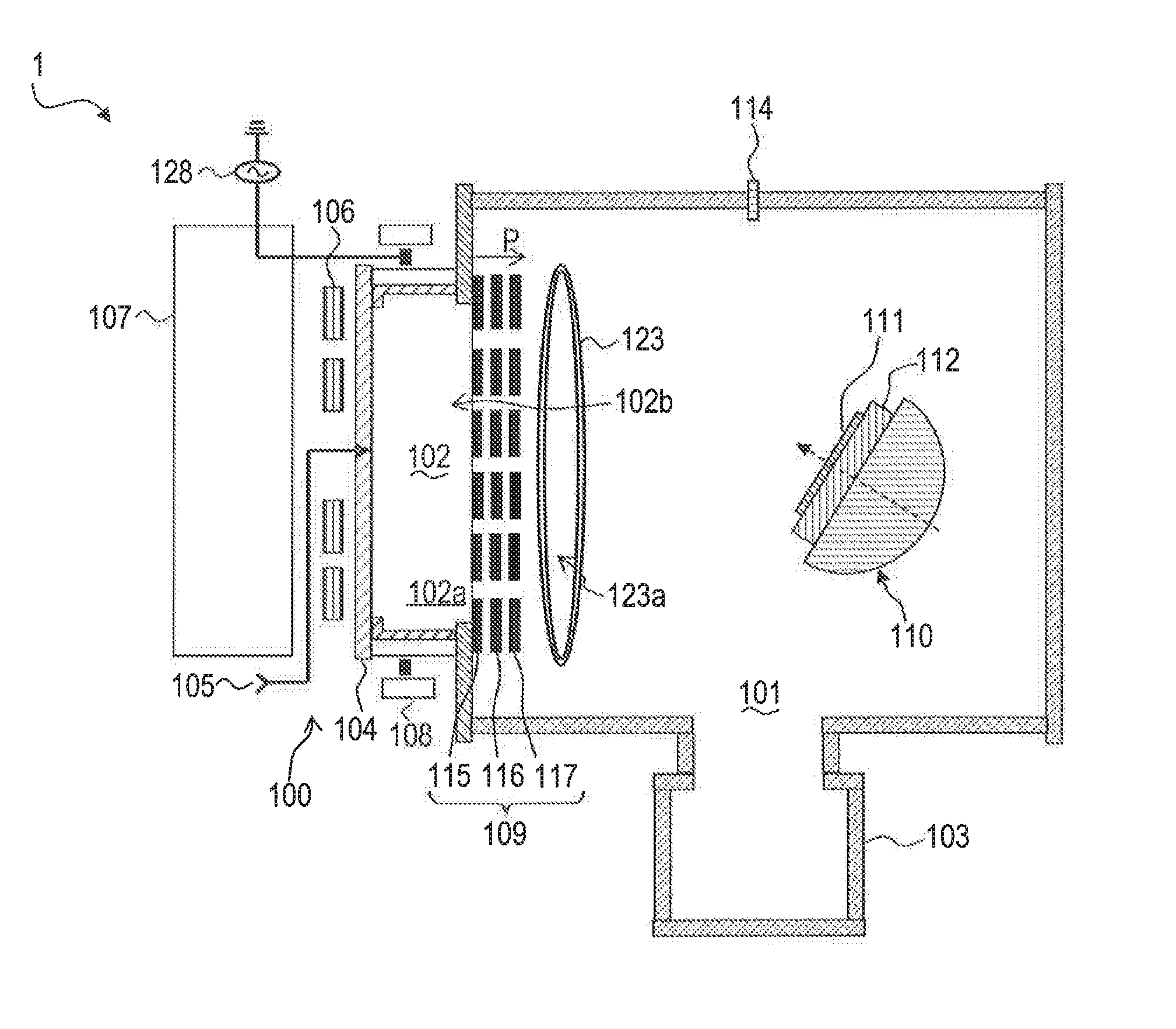
[0021]FIG. 1 shows a schematic diagram of an ion beam etching apparatus according to this embodiment. An ion beam etching apparatus 1 includes a processing chamber 101 and an ion beam generator 100 provided so as to radiate ion beams into the processing chamber 101. The ion beam generator 100 and the processing chamber 101 are connected to each other, and thus the ion beams generated by the ion beam generator 100 are introduced into the processing chamber 101.

[0022]Inside the processing chamber 101, a substrate holder 110 capable of holding a substrate 111 is provided so as to receive the ion beams radiated from the ion beam generator 100. The substrate holder 110 provided inside the processing chamber includes an ESC (Electrostatic Chuck) electrode 112 on the ion beam-incident side. The substrate 111 is placed on the ESC electrode 112 and electrostatic attraction and held by the ESC electrode 112. The substrate holder 110 can be arbitrarily tilted with respect to the ion beams. Als...

second embodiment

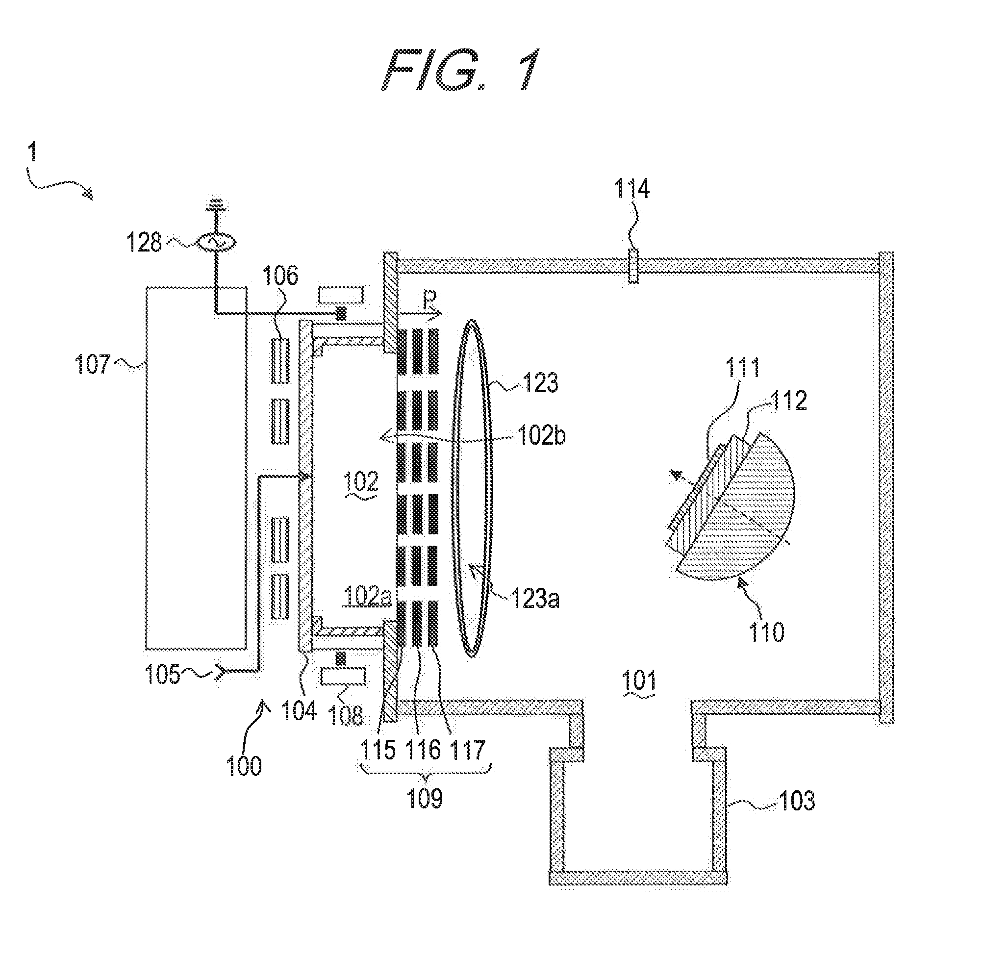
[0051]Although, in the first embodiment, the lamp heater 123 disposed at a distance from the second ring 120 is used as the heating unit configured to heat the third electrode 117 from outside of the plasma generation chamber 102, the heating unit is not limited thereto. The heating unit may be one capable of heating the third electrode 117, and is preferably one capable of heating the third electrode 117 and the fixing member 121. As the above heating unit, any type of unit may be used, such as resistance heating type, induction heating type, dielectric heating type and radiation heating type, for example, as long as predetermined members can be heated. In this embodiment, description is given of a configuration using a heating wire that is an example of the resistance heating type, as the above heating unit.

[0052]FIG. 6 is a schematic diagram for explaining the above heating unit according to this embodiment. In FIG. 6, a heating wire 124 is provided along a circumferential direct...

third embodiment

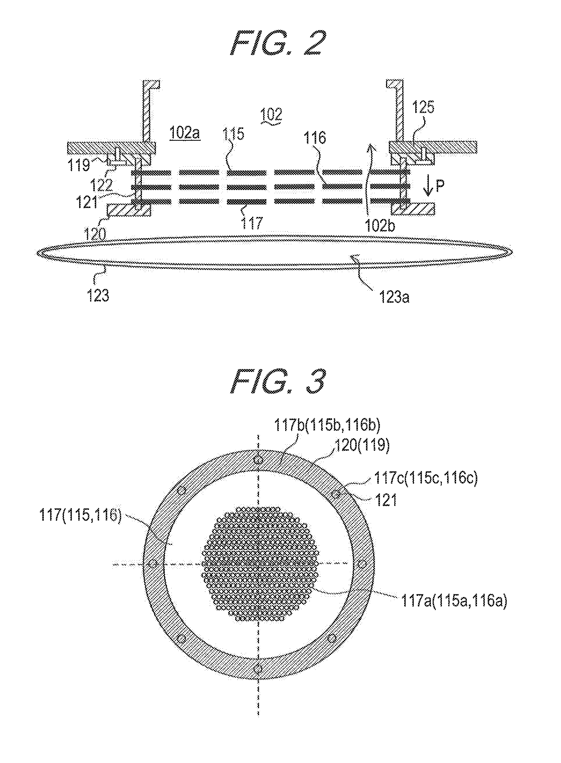
[0055]The fixing member 121 may be configured so as to be slidable with respect to at least one of the first ring 119 and the second ring 120. With such a configuration, the fixing member 121 can be freely elongated and contracted regardless of coefficients of thermal expansion of the first ring 119 and the second ring 120. Thus, the load applied to the fixing member 121 and the first to third electrodes 115 to 117 can be further reduced.

[0056]FIG. 7 is a diagram showing the second ring 120 when the fixing member 121 is configured to be slidable with respect to the second ring 120. FIG. 7 shows a state of the second ring 120 as seen from the first ring 119 side.

[0057]In FIG. 7, opening portions 126 are formed so as to make the fixing member 121 slidable in a radial direction of the second ring 120, instead of the concave part 120a in the first embodiment, on the circumference of the second ring 120. The opening portions 126 are for fixing the other ends of the fixing members 121, an...


PUM


Abstract

An ion beam etching apparatus includes: a processing chamber connected to the plasma generation chamber including an internal space; a plasma generating unit configured to generate plasma in the internal space; an extracting unit configured to extract ions from the plasma, from the internal space to the processing chamber, the extracting unit including first, second and a third electrodes, each of which has a plurality of ion passage holes; a first ring member provided closer to the plasma generation chamber; a second ring member provided closer to the processing chamber; a fixing member having one end and another end, the fixing member penetrating the first, second and third electrodes, and having the one end connected to the first ring member and the other end connected to the second ring member; and a heating unit configured to heat the third electrode from outside of the plasma generation chamber.

Description

CROSS-REFERENCES TO RELATED APPLICATIONS[0001]This application is based upon and claims the benefit of priority of the prior Japanese Patent Application No. 2015-111701, filed Jun. 1, 2015. The contents of the aforementioned application are incorporated herein by reference in their entireties.BACKGROUND OF THE INVENTION[0002]Field of the Invention[0003]The present invention relates to an ion beam etching apparatus and an ion beam generator.[0004]Description of the Related Art[0005]In a technology to manufacture a semiconductor device, ion beam etching (hereinafter also referred to as IBE) is used to form various patterns. Such an IBE apparatus generates plasma by introducing gas into an ion source and using appropriate means, extracts ions from the plasma and performs etching by irradiating an object to be processed with the ions.[0006]The IBE apparatus generally uses a plurality of grids to extract ions from plasma. The plurality of grids are generally fixed at their ends to preven...

Claims


Application Information

Patent Timeline
IPC IPC(8): H01J37/32
CPCH01J37/32532H01J2237/334H01J37/32715H01J37/32321H01J37/32357H01J37/32422H01J37/32522
Inventor OKAMOTO, NAOYUKIKODAIRA, YOSHIMITSUYASUMATSU, YASUSHI
Owner CANON ANELVA CORP
Why Eureka
Try Eureka