Stator of motor, stator unit and manufacturing method thereof

a technology of stator unit and motor, which is applied in the direction of dynamo-electric machines, electrical apparatus, magnetic circuit shapes/forms/construction, etc., can solve the problems of increased equipment cost, difficult manufacturing process, long time, etc., and achieves the effect of saving manufacturing cost, reducing time consumption, and reducing manufacturing costs

Inactive Publication Date: 2016-12-01
FAN YANG FUNG
View PDF7 Cites 5 Cited by
  • Summary
  • Abstract
  • Description
  • Claims
  • Application Information

AI Technical Summary

Benefits of technology

[0009]As described above, according to one embodiment of the present disclosure, the radial slot tooth comprises at least one aligning hole. The extension direction of the aligning hole is substantially equal to the extension direction of the first engaging portion and the second engaging portion. The boot portion is arc-shaped and comprises a concave arc surface facing to the center of the stator of motor. Thus, in the assembly process, each stator unit can sleeve on a corresponding fixture through the aligning hole and the concave arc surface so that each stator unit can be positioned to avoid shaking or displacement.
[0013]Thus, the manufacturing cost is saved effectively, the process is simplified, and the assembling time of the stator of motor is shortened. Furthermore, since the bushing sleeves on the outside of the extension arm, the boot portion can increase the permeability of the stator of motor, improve the operation characteristics of the motor and increase smoothness of operation.
[0014]In addition, the stator of motor can be assembled by engaging the first engaging portion with the second engaging portion so that the stator units can be connected to form the ring. Thus, there is no need to assemble additional fixtures or frames to prevent detachment of each stator unit, and further reduce costs.

Problems solved by technology

Thus, its manufacturing process is difficult, the procedure is complicated, the processing time is long, and the cost of the equipment is increased.

Method used


Image

  • Stator of motor, stator unit and manufacturing method thereof
  • Stator of motor, stator unit and manufacturing method thereof
  • Stator of motor, stator unit and manufacturing method thereof

Examples


Embodiment Construction

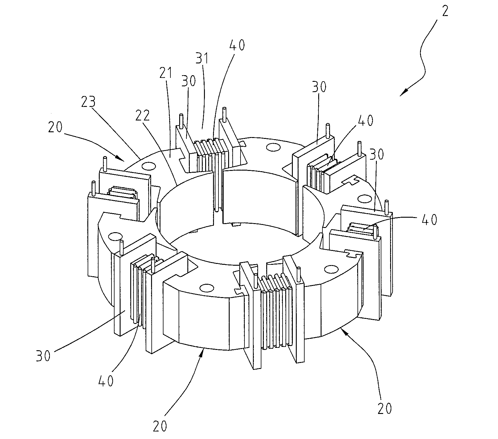
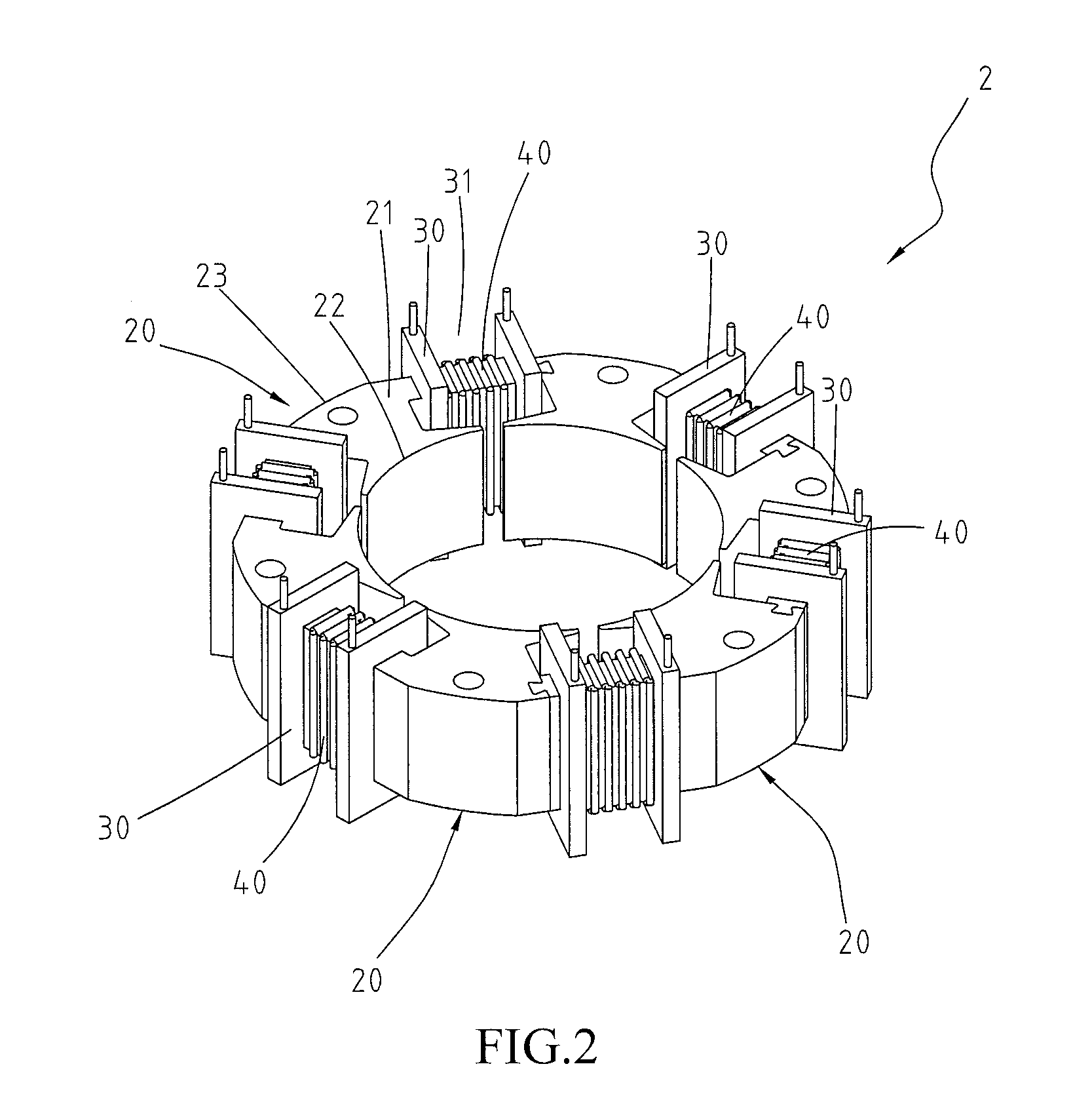
[0025]Please refer to FIGS. 2 and 3. The stator of motor 2 comprises a plurality of stator units 20 and a plurality of bushings 30. The stator units 20 are connected together to form a ring. In this embodiment, each stator unit is one piece component. Alternatively, as shown in FIG. 7, in another embodiment, each stator unit can be a module by stacking up a plurality of soft magnetic members 201. The soft magnetic member 201 may be a sheet shape and made of at least one of soft magnetic materials such as iron, cobalt, nickel, or silicon steel. The soft magnetic members 201 can be combined by an adhesive or riveted joint. Or, in other embodiment, each stator unit 20 can be a single soft magnetic sheet. Multiple stator units 20 are stacked up into a module, and multiple modules can be connected to form a ring shape. It is to be noted that, the assembling structure of the stator units 20 and the ring is not intended to limit the scope of the instant disclosure.

[0026]Each stator unit 20...


PUM


Abstract

A stator of motor includes a plurality of stator units and a plurality of bushings. The stator units are connected to form a ring. Each stator unit includes a radial slot tooth and an extension arm. The radial slot tooth includes a boot portion, an external circumference opposed to the boot portion, a first side and a second side opposed to the first side. The boot portion is connected to the external circumference through the first side and the second side. The first side has a first engaging portion. The extension arm extends from the second side and the end of the extension arm has a second engaging portion. The first engaging portion of one stator unit is in engagement with the second engaging portion of the adjacent stator unit. The bushings sleeve on the outside of the extension arms respectively, and each bushing is wound by a coil.

Description

CROSS-REFERENCES TO RELATED APPLICATIONS[0001]This non-provisional application claims priority under 35 U.S.C. §119(a) on Patent Application No. 104117265 filed in Taiwan, R.O.C. on 2015 May 28, the entire contents of which are hereby incorporated by reference.BACKGROUNDTechnical Field[0002]The present disclosure relates to a motor component, in particular, relates to a stator of motor, stator unit and manufacturing method thereof.Related Art[0003]As the development of technology, the needs of the electric motor (also known as motor) increase. The main function of the motor is to convert electrical energy into mechanical energy including kinetic energy for driving other apparatus. Most of electric motor can produce energy through the magnetic field and the electric current. The electrical motor mainly includes a stator and a rotor. The stator disposed in the motor housing is stationary while the rotor is driven by the interaction of magnetic fields of stator and the rotor to rotate ...

Claims


Application Information

Patent Timeline
Patent Type & Authority Applications(United States)
IPC IPC(8): H02K3/28H02K15/02H02K15/04H02K1/14
CPCH02K3/28H02K15/0435H02K15/02H02K1/148H02K15/022H02K15/066
Inventor FAN, YANG-FUNG
Owner FAN YANG FUNG
Why Eureka
Try Eureka