Spring driven injector apparatus with needle insertion

a technology of injector and spring, which is applied in the direction of intravenous devices, infusion needles, other medical devices, etc., can solve the problems that the injector may not be generally intended, and achieve the effect of minimising the device profil

Active Publication Date: 2016-12-08
OWEN MUMFORD
View PDF3 Cites 51 Cited by
  • Summary
  • Abstract
  • Description
  • Claims
  • Application Information

AI Technical Summary

Benefits of technology

[0006]Arrangements in accordance with embodiments of the invention are particularly advantageous for high volume and / or high viscosity medicaments. In the case of high volume injections the medicament can be delivered in several neighbouring locations to allow faster medicament dissipation while avoiding or minimising the risk of a bolus forming. In the case of high viscosity injections, the plurality of needles provide a larger flow path and may reduce the drug delivery rate through each needle so as to reduce the pressure build up in the cartridge.
[0027]The delivery mechanism may comprise: a plunger having a forward end extending into the cartridge for expressing a dose in use and a rearward end including a profiled head; a biasing element arranged to urge the plunger towards it forward position; a latch plate fixed relative to the housing and having a slot arranged to receive the profiled head of the plunger and retain the plunger in a rearward position against the force of the biasing element. The delivery mechanism may be actuated in a transverse direction relative to the housing to move the needle in the transverse direction to the delivery position, and release the plunger from the latch plate such that the biasing element may urge the plunger forward in the longitudinal direction.
[0029]The delivery mechanism may include a trigger member arranged to resiliently deflect the profiled head of the plunger to release the plunger from the latch plate. The, or each, cartridge may be fixed relative to the housing. The, or each, needle is connected to the, or each, cartridge by at least one flexible conduit. As such, the needle(s) may be able to move relative to the cartridge. Such an arrangement may enable the profile of the device to be minimised.

Problems solved by technology

For example, whilst there may be some nominal delay or overlap in the delivery, a bolus injector may not generally be intended to provide a sequence of distinct / separate injections from the plurality of cartridges.

Method used


Image

  • Spring driven injector apparatus with needle insertion
  • Spring driven injector apparatus with needle insertion
  • Spring driven injector apparatus with needle insertion

Examples


Embodiment Construction

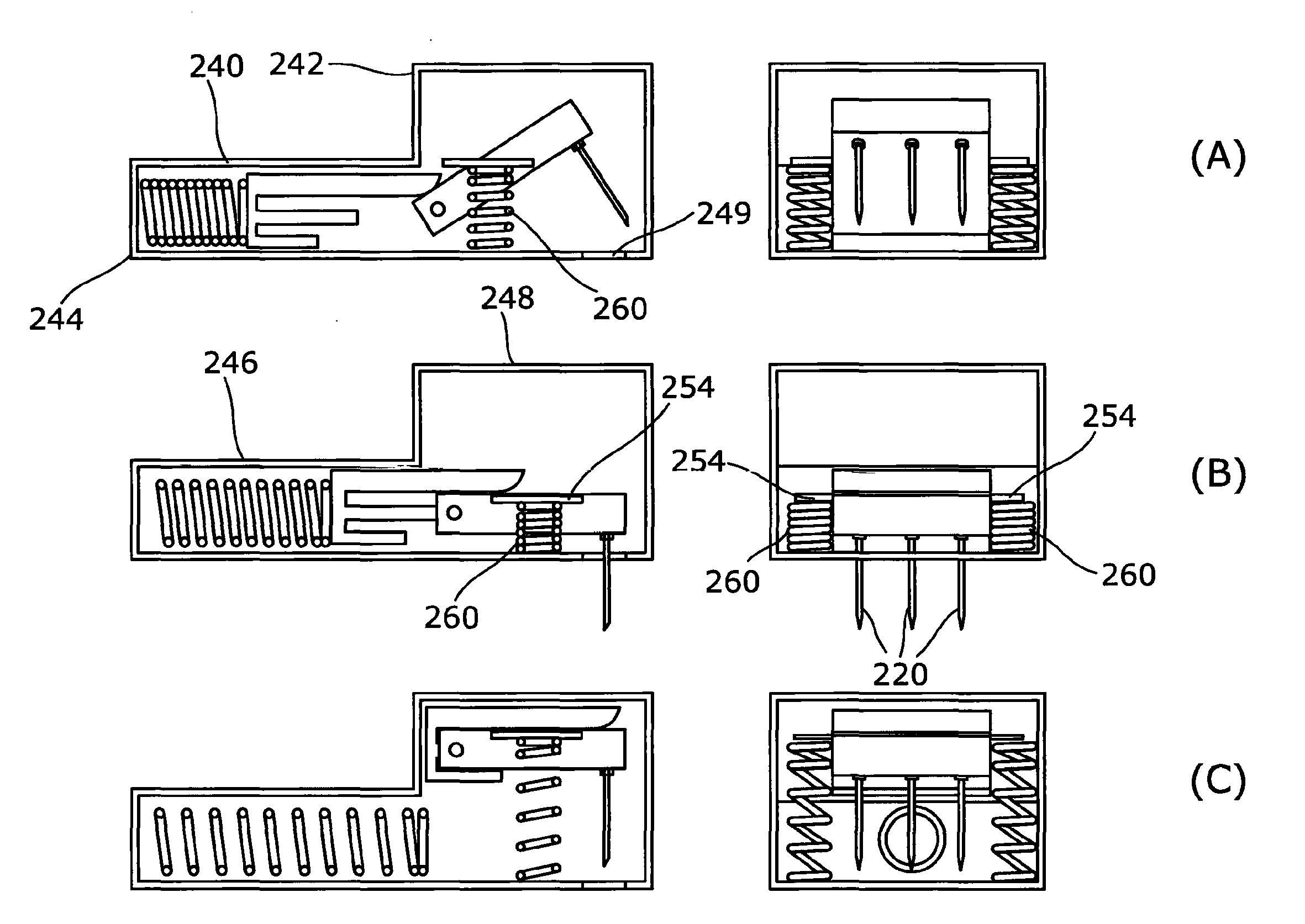
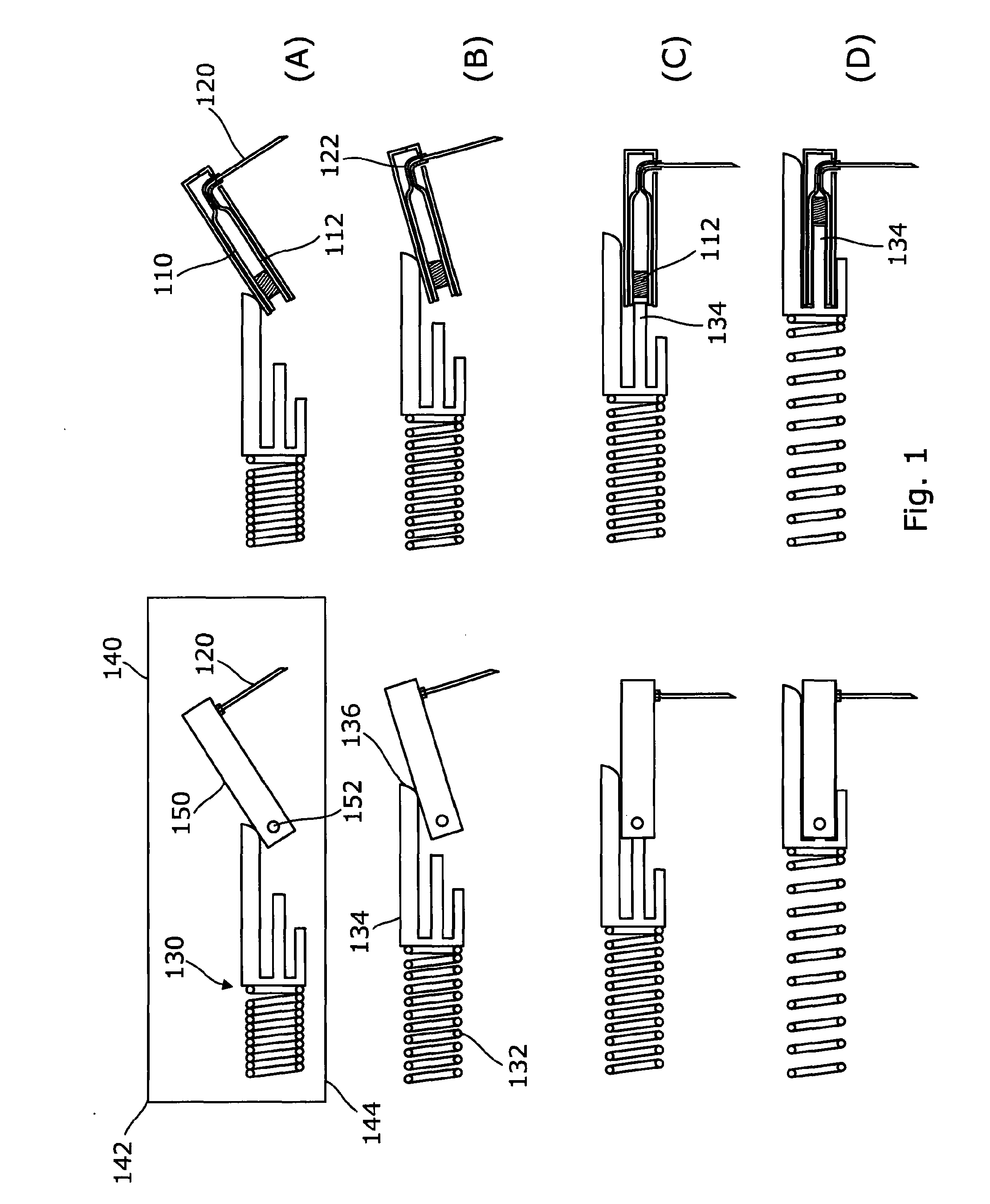
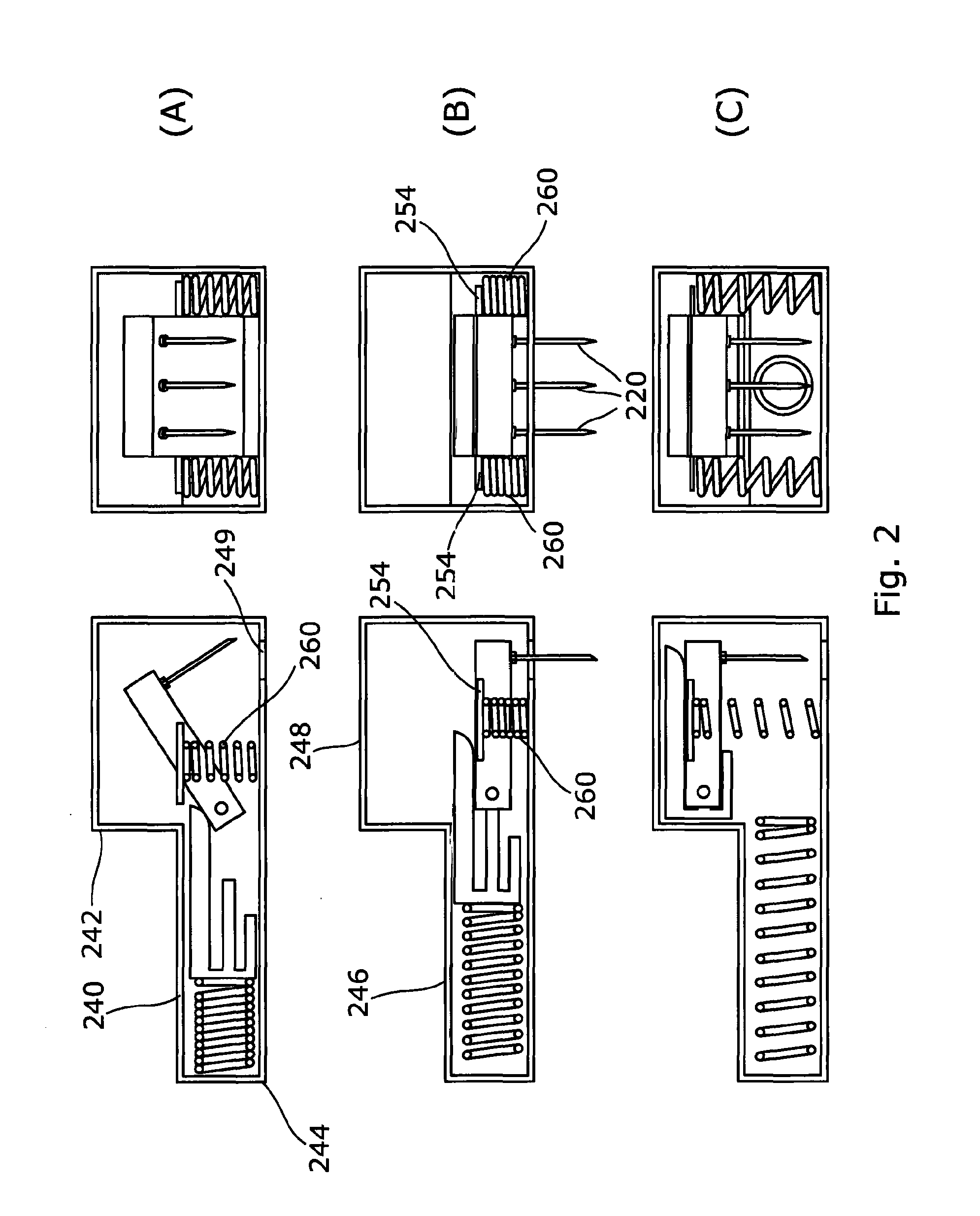
[0048]A number of embodiments of the invention are described below, it will be noted that in each embodiment the injector device is generally provided with an elongate housing which receives at least one cartridge. The longitudinal axis of the cartridge and housing are generally aligned so as to provide a low profile device. In contrast to conventional pen type injection devices the embodiments all provide an arrangement in which the delivery needle(s) project out of the housing in a transverse direction such that the device may be worn against the skin during medicament delivery.

[0049]The disclosed embodiments generally incorporate at least one aspect of the invention. In each embodiment like reference numerals (but with the first digit of the reference numerals is increased in accordance with the figure number) are used for like components for the ease of understanding.

[0050]An injection device according to a first embodiment is shown in FIG. 1 and comprises at least one cartridge...


PUM


Abstract

An injection device is disclosed which comprises a housing (140, 240, 440, 740) for a plurality of cartridges (110,310,410,810) each containing a medicament to be administered to a patient. A plurality of needles (120, 220, 320, 420, 720, 820) may be provided in communication with the plurality of cartridges. A delivery mechanism is arranged to deliver medicament through the plurality of cartridges via the plurality of needles. An injection device may comprise a drive member (130) having a cam surface (136) configured to engage a surface of a carrier (150) and rotate the carrier about a pivot (152) and at least one plunger (134) arranged to engage a cylinder in the cartridge.

Description

FIELD OF THE INVENTION[0001]This invention relates to an injection apparatus and in particular, but not exclusively, to an injection apparatus arranged to be worn against the skin of a user.BACKGROUND OF THE INVENTION[0002]Injection devices, such as the Owen Mumford Autopen®, are commonly used by patients to self-administer injections of medicament. Such devices are typically provided in a pen-like body which contains, defines or receives a cartridge (which it will be understood may comprise a syringe) of medicament. The injection device generally comprises a delivery mechanism which is arranged to dispense the medicament via a needle in response to a user pressing a button or trigger. Depending upon the type of device and or medicament to be delivered the injection device may be arranged to deliver the entire contents of the cartridge or a selected dose therefrom. In some injection devices the delivery mechanism may also be arranged to move the needle between a retracted and delive...

Claims


Application Information

Patent Timeline
Patent Type & Authority Applications(United States)
IPC IPC(8): A61M5/32A61M5/315A61M5/42A61M5/19A61M5/20
CPCA61M5/3287A61M5/19A61M5/2033A61M5/3298A61M2005/3289A61M5/3202A61M5/31578A61M2005/206A61M5/422A61M5/1424A61M5/16809A61M5/204A61M5/24A61M5/2429A61M5/3146A61M5/31548A61M5/31553A61M5/3156A61M5/3159A61M5/31593A61M5/329A61M5/344A61M2205/19A61M2005/14256A61M5/1454A61M2005/1581A61M5/14248A61M2005/14252
Inventor ANDERSON, OLIVERCOWE, TOBYVARDE, ANDREWMARSHALL, JEREMY
Owner OWEN MUMFORD
Why Eureka
Try Eureka