Wheel drive motor and in-wheel motor drive assembly

Active Publication Date: 2016-12-08
NTN CORP
View PDF1 Cites 13 Cited by
  • Summary
  • Abstract
  • Description
  • Claims
  • Application Information

AI Technical Summary

Benefits of technology

[0020]According to the present invention, the in-wheel motor drive assembly can be housed in the hollow area of the road wheel without great difficulty, and the wheel drive motor can fit in a narrow and small wheel housing and can be even installed in automobiles having severe layout constraints. Also, in the grinding process of the motor shaft, the outer circumferential surfaces of t

Problems solved by technology

However, the inventors of this invention have discovered that the aforementioned conventional in-wheel motor drive assemblies still have issues to be improved.
It is difficult to increase the radial size of the motor under the constraint that the motor needs to fit inside the road wheel, but the axial size of the motor should be extended to provide a required torque.
Thus, referring to FIG. 6, the axial length Ls of the motor shaft 103 is required to be shorter in terms of arrangement; however, it is difficult to shorten the bearing span between the bearings, which rotatably support the opposite ends of the motor shaft, to provide the required torque.
Secondly, the speed of a vehicle (automobile) equipped with the in-wheel motor drive assembly changes from 0 km/h to a high speed range more than 100 km/h.
Focusing on a suspension device to which the in-wheel motor drive assembly is attached, it is appreciated from

Method used


Image

  • Wheel drive motor and in-wheel motor drive assembly
  • Wheel drive motor and in-wheel motor drive assembly
  • Wheel drive motor and in-wheel motor drive assembly

Examples


Example

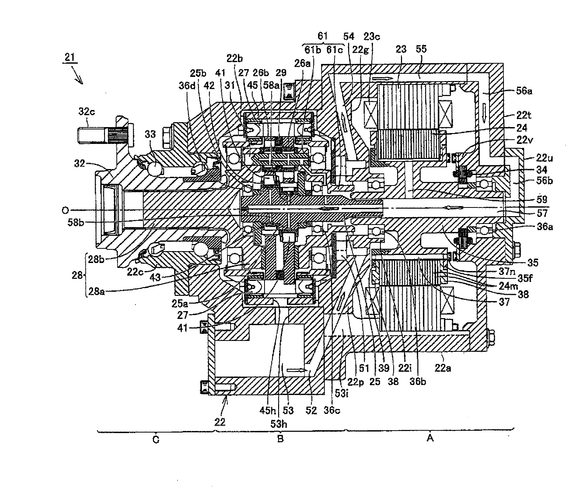
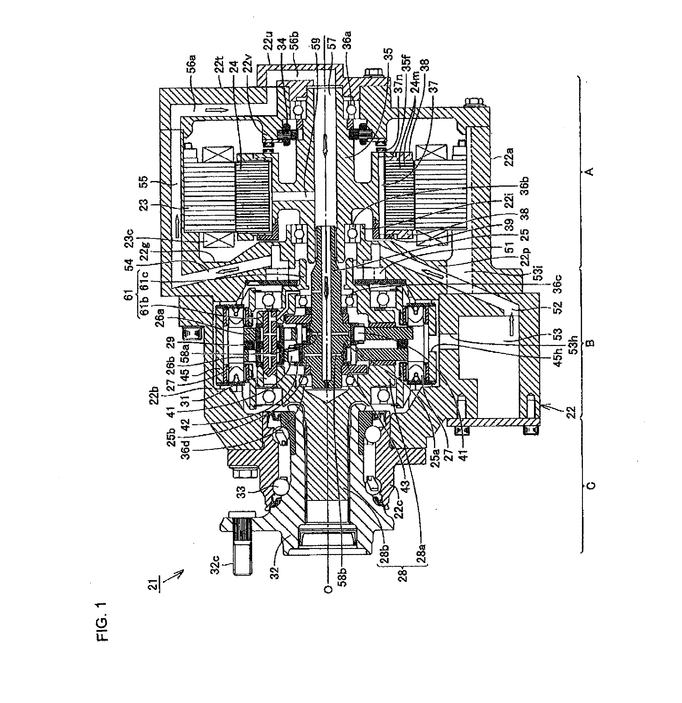
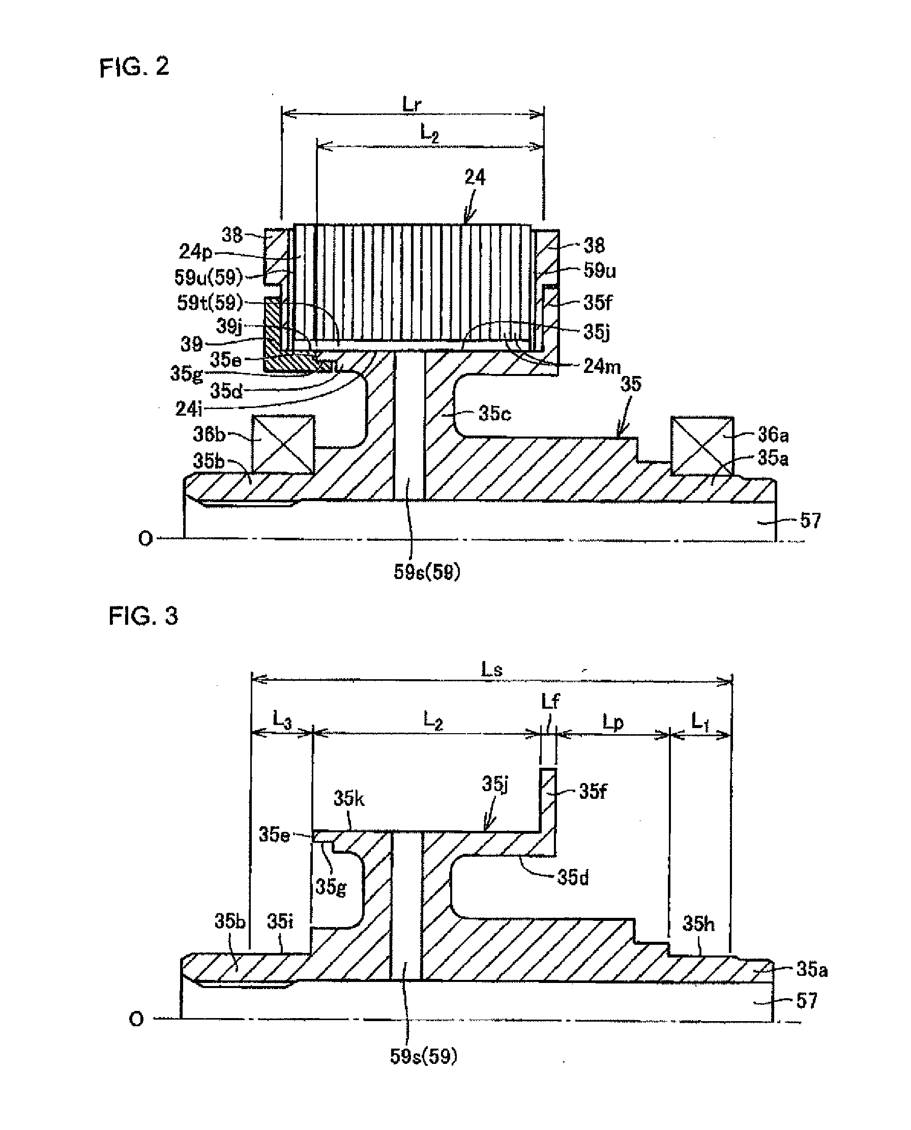
[0027]With reference to the accompanying drawings, an embodiment of the present invention will be described below. FIG. 1 is a vertical cross-sectional view of an in-wheel motor drive assembly adopting a wheel drive motor according to the embodiment of the present invention. FIG. 2 is a vertical cross-sectional view showing a motor shaft, a rotor, and a bearing taken out from FIG. 1. FIG. 3 is a vertical cross-sectional view showing the motor shaft taken out from FIG. 1. An in-wheel motor drive assembly 21 includes, as shown in FIG. 1, a motor section A that generates driving force, a speed reducing section B that reduces the rotational speed of the motor section A and outputs the reduced rotational speed, and a wheel hub bearing section C that transmits the output from the speed reducing section B to a driving wheel. The motor section A, speed reducing section B, and wheel hub bearing section C are coaxially aligned in this order in the direction of an axis O.

[0028]The motor sectio...


PUM


Abstract

The wheel drive motor according to the invention includes a motor shaft (35) having a large diameter portion (35d) located at a central part in the axial direction and a small diameter portion (35b) located on a first side in the axial direction, a bearing (36b) rotatably supporting the small diameter portion (35b), and a rotor (24) secured to an outer circumferential surface (35j) of the large diameter portion (35d). An end part (24p) of the rotor (24) located on the first side in the axial direction projects over an end face (35e) of the large diameter portion (35d) located on the first side in the axial direction toward the side on which the small diameter portion (35b) is.

Description

TECHNICAL FIELD[0001]The present invention relates to a wheel drive motor that is built in an in-wheel motor drive assembly or in other drive assemblies to drive a wheel.BACKGROUND ART[0002]As a conventional well-known wheel drive motor for driving a wheel, for example, disclosed are in-wheel motor drive assemblies in Japanese Unexamined Patent Application Publication Nos. 2012-148725 (PTL 1) and 2009-063043 (PTL 2). FIG. 5 shows an in-wheel motor drive assembly 101 as disclosed in PTL 1 and PTL 2, that is mainly composed of a motor section 101A including a motor, a speed reducing section 101B including a cycloid reducer, and a wheel hub bearing section 101C rotatably supporting a wheel hub 108. The motor section 101A has a motor casing 102 that rotatably supports opposite end parts 103a, 103c of a motor shaft 103 using rolling bearings 104, 105. A hollow cylindrical rotor 106 is fixedly coupled on an outer circumferential surface at a central part 103b of the motor shaft 103. An ou...

Claims


Application Information

Patent Timeline
IPC IPC(8): B60K7/00B60B27/00H02K7/08B60K17/04H02K1/32H02K9/19
CPCB60K7/0007H02K1/32B60B27/00H02K7/08B60K17/043H02K9/19H02K1/30H02K2213/03H02K7/006H02K7/116Y02T10/64
Inventor UOZUMI, TOMOHISAKURODA, MASARUSUZUKI, KENICHI
Owner NTN CORP
Why Eureka
Try Eureka