Valve with locking mechanism, and integrated valve

a locking mechanism and valve technology, applied in the direction of diaphragm valves, valve housings, engine diaphragms, etc., can solve the problems of excessive manufacturing costs, difficult to connect the valve, and complicate the internal structure of the handle and the slide member, so as to reduce the number of components and optimize the shape of the cutout stepped face

Active Publication Date: 2016-12-08
KITZ SCT
View PDF2 Cites 6 Cited by
  • Summary
  • Abstract
  • Description
  • Claims
  • Application Information

AI Technical Summary

Benefits of technology

[0019]According to the first aspect of the invention, the cutout stepped face is formed on a part of the outer periphery of the valve body and the locking plate is placed in this cutout stepped face. This prevents the locking plate from projecting horizontally from the valve body or moving toward the interior of the valve body, thus offering the compact valve with the locking mechanism that reduces an unnecessary portion of a housing space for the locking plate to the minimum and also offering the handle with better operability. When this valve is connected to a place where valve units making up an integrated valve are arranged in close formation, the valve does not interfere with an adjacent valve unit. In addition, because the locking hole is faced the upper surface area of the valve body to allow locking, a locking member's interfering with an adjacent valve unit, etc., upon locking can be avoided.
[0021]The locking plate pivotally attached rotatably is guided in its rotation along the cutout stepped face serving as a sliding face for the locking plate. This allows configuring a locking mechanism of a simple structure not requiring any member supporting the slide movement of the locking plate, such as a frame and spring, thus requiring less number of components.
[0022]According to the second aspect of the invention, the cutout allowing the rotation of the locking plate is formed on a part of the rotating plate and the outer peripheral lower surface of the part of rotary plate other than the cutout serves as the locking portion. This allows configuring a misoperation preventing mechanism of an extremely simple structure that causes the locking portion to lock the locking plate when the locking plate is in either the full-close state or full-open state to prevent it from rotating, thereby prevents a worker's misoperation that the worker mistakenly locks the locking plate when it is in a state other than the full-close state or full-open state.
[0023]According to the third aspect of the invention, the enclosure of the valve body is formed into a cylindrical shape and the rotation area of the locking plate is confined to the area almost along the radial direction of the cylindrical enclosure. As a result, the whole rotation area of the locking plate is located within a square area circumscribing the circular plane shape of the cylindrical enclosure in a plan view, which prevents the locking plate from interfering with an adjacent valve unit and allows the valve to be compactified significantly. This offers a very preferable locking mechanism of a valve unit connected an integrated valve.
[0024]The stepped portion of the cutout stepped face serves as the rotation locking surface that prevents the locking plate from rotating when it is in either the full-open state or full-close state. As a result, the shape of the cutout stepped face can be optimized or minimized so as to match the shape of the locking plate, and when the locking plate is placed in the cutout stepped face, the stepped portion comes in contact with aside face of the locking plate to function as a stopper, thereby ensures that the locking plate is placed properly in the cutout stepped face.
[0025]According to the fourth aspect of the invention, the indication portion seen from the valve's upper surface side, which indication portion is particularly preferable for indicating a state of valve opening or closing of an integrated valve, can be formed in a simple structure in which the opening peek is formed on the rotary plate of the handle body. The opening peek is formed on the handle and indicates the state of opening or closing in interlocking action with a handle operation. A worker, therefore, easily recognizes the state of opening or closing when operating the handle.

Problems solved by technology

When it is tried to connect a valve unit having a lock mechanism projecting horizontally from the upper surface area of a valve body to a place where valve units making up an integrated valve compactified as much as possible are arranged in close formation, a portion projecting horizontally from an occupied area occupied by the valve unit interferes with an adjacent valve unit, which makes valve connection impossible or limits the place or direction of valve connection.
This significantly complicates the internal structure of the handle and the structure of the slide member.
The lock mechanism of patent document 2 thus requires excessively large manufacturing costs.
This results in an unpleasant operation feeling and inferior operability.
According to the lock mechanism of patent document 3, the lock hole formed on the operating handle impairs the operability of the handle and complicates the shape of the handle.
When the lock plate is pivotally and rotatably attached to the valve body, rotating the lock plate causes it to project horizontally from the upper surface area of a base, in which case the lock plate may interfere with an adjacent valve unit.

Method used


Image

  • Valve with locking mechanism, and integrated valve
  • Valve with locking mechanism, and integrated valve
  • Valve with locking mechanism, and integrated valve

Examples


Embodiment Construction

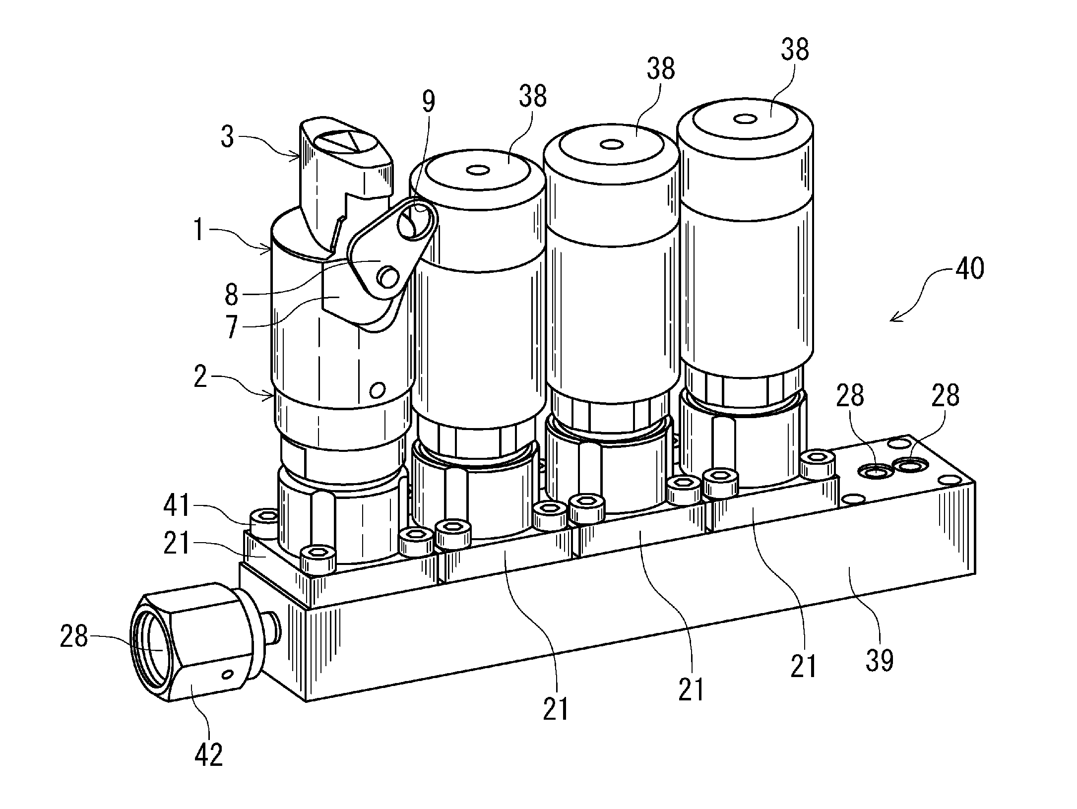
[0037]An example of embodiments of a valve with a locking mechanism and an integrated valve according to the present invention will now be described in detail, referring to drawings. The valve with the locking mechanism of the present invention is applied in particular, preferably to an opening / closing manual valve used in a gas supply system of a semiconductor manufacturing apparatus and to an integrated valve including the opening / closing manual valve.

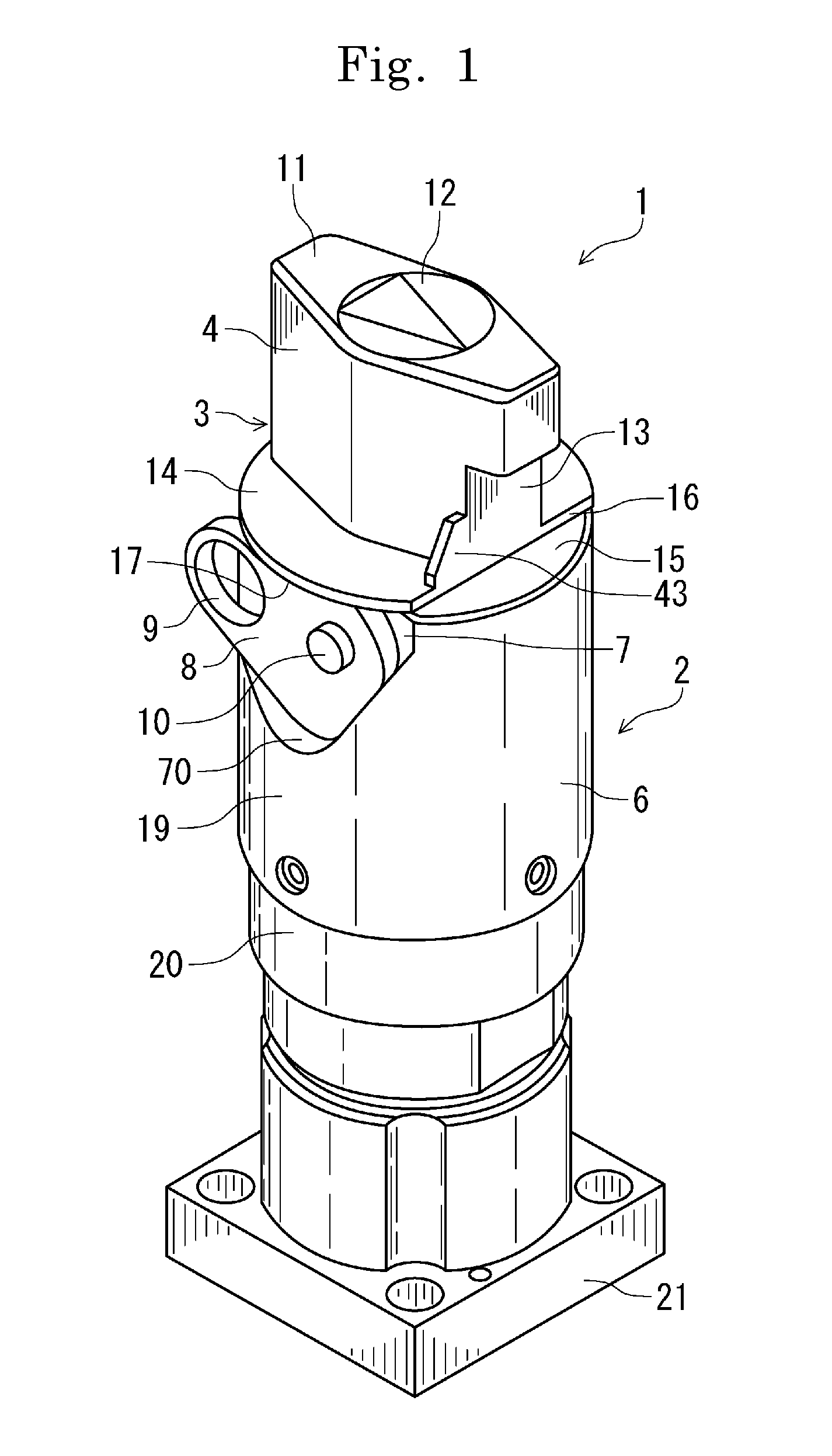
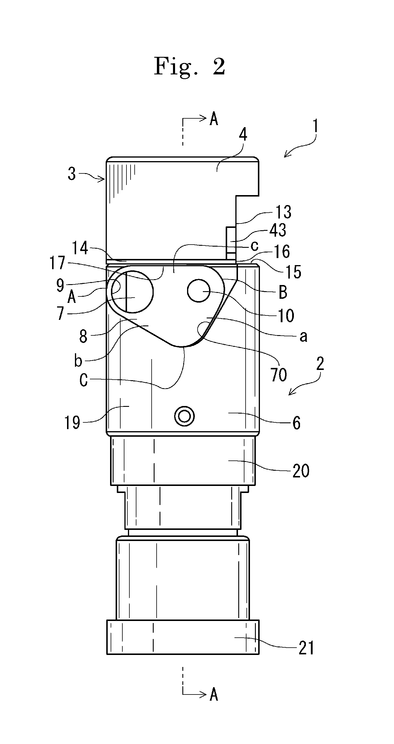
[0038]FIG. 1 is a perspective view showing an external view of a valve 1 with a locking mechanism of the present invention, the valve 1 having a handle in its open position (full-open state). On top of a valve body 2, a handle body 3 having a knob 4 is disposed to be rotated freely. The valve body 2 has a valve shaft 29 built therein for opening and closing a valve piece (diaphragm) 26, which will be described later. On a part of the outer periphery 6 of the valve body 2 located below the handle body 3, a cutout stepped face 7 is for...


PUM


Abstract

A valve with a locking mechanism and an integrated valve are provided. The valve includes a handle body having a knob, the handle body being disposed rotatably on top of a valve body housing a valve shaft for opening and closing a valve piece. A cutout stepped face is formed on a part of the outer periphery of the valve body located under the handle body. A locking plate having a locking hole is placed rotatably in the cutout stepped face via a pivotally attaching portion, and when the locking plate is rotated to either a position at which the valve body is in a full-close state or a position at which the valve body is in a full-open state, the locking hole is faced the upper surface area of the valve body to allow locking.

Description

FIELD OF THE INVENTION[0001]The present invention relates to a valve with a locking mechanism and to an integrated valve, and, for example, relates to a manual valve with a locking mechanism used for an integrated gas supply system of a semiconductor manufacturing apparatus and to an integrated valve having the manual valve.DESCRIPTION OF THE RELATED ART[0002]In a gas supply system of a semiconductor manufacturing apparatus, an integrated valve is used as a gas stick, etc., which is an integrated valve unit having a channel, to which various valves, such as a manual valve, automatic valve, and purging valve, a filter, a regulator, a pressure sensor, a mass-flow controller, etc., are connected in series. Such integrated valves are arranged compactly in parallel with each other to reduce the size of the gas supply system as much as possible.[0003]A manual valve connected to such an integrated valve is usually disposed at the inlet or outlet of the channel of the integrated valve and i...

Claims


Application Information

Patent Timeline
Patent Type & Authority Applications(United States)
IPC IPC(8): F16K35/02F16K31/60
CPCF16K31/60F16K35/025F16K31/607F16K35/00F16K37/0008F16K7/16Y10T137/7256F16K7/12F16K27/0236F16K31/44F16K35/04F16K35/06F16K35/02
Inventor IIZUKA, HISANOBU
Owner KITZ SCT
Why Eureka
Try Eureka