Distributed mode louspeaker damping oscillations within exciter feet

a louspeaker and vibrating panel technology, applied in the direction of transducer types, frequency/directions obtaining arrangements, electrical equipment, etc., can solve the problems of inability and unsightly holes, and achieve the effect of improving the performance of the distributed mode vibrating panel loudspeaker

Active Publication Date: 2016-12-08
AMINA TECH
View PDF3 Cites 11 Cited by
  • Summary
  • Abstract
  • Description
  • Claims
  • Application Information

AI Technical Summary

Benefits of technology

[0011]One solution is to remove the central region from the resonant panel entirely. Whilst this improves the performance of the distributed mode vibrating panel loudspeaker by increasing the amplitude of the frequency response in the affected area, the resulting hole can be unsightly and is typically covered with a fabric cover. In some embodiments of flat panel loudspeakers, it is desirable to hide the loudspeaker in a surface such as a wall by applying a thin covering over the loudspeaker, such as plaster. This is not possible with a hole in the resonant panel. Therefore, another solution is required.
[0012]In accordance with an aspect of the present invention there is provided a flat panel loudspeaker comprising a resonant panel, an exciter comprising a foot generally cylindrical in shape, coupled to the resonant panel and defining an inner region of the resonant panel. The exciter is drivable to vibrate the resonant panel via the foot, whereby to produce a sound. The flat panel loudspeaker further comprises a damping member coupled to the foot and in contact with the inner region of the resonant panel and arranged inside the foot to generally brace against the vibration of the resonant panel so as to damp a response of the resonant panel in the inner region to a vibration from the exciter.
[0013]Thus, oscillations in the inner region of the resonant panel can be rapidly damped by the provision of a separate damping member in contact with the inner region of the resonant panel. Rapid damping of the oscillations in the inner region of the resonant panel ensures that the oscillations do not unacceptably damp the oscillations in the outer region of the resonant panel and therefore also ensure that the frequency response of the flat panel loudspeaker is not undesirably damped in parts of the frequency response.
[0020]The damping member may comprise a plurality of fins extending in a plane substantially perpendicular to a plane of the resonant panel. Thus, the fins provide a damping member which may be lightweight and can damp oscillations of the resonant panel in the direction of the plane of the fins.
[0022]The fins may have a generally tapered shape away from the resonant panel. Thus, the fins are narrower near the foot and wider near the centre of the inner region. This shape gives effective dissipation of resonant energy.
[0024]The foot may have a plurality of notches extending from the resonant panel towards the exciter. Thus, the increased stiffness of the foot due to the damping member being coupled to the foot (which otherwise dampens the response of the panel across the acoustic spectrum) may be at least partly counteracted by reducing the stiffness of the foot by introducing notches into the structure of the foot. This may reduce the effect of the damping member itself on the oscillations induced by the exciter in the region outside the inner region of the resonant member.

Problems solved by technology

Whilst this improves the performance of the distributed mode vibrating panel loudspeaker by increasing the amplitude of the frequency response in the affected area, the resulting hole can be unsightly and is typically covered with a fabric cover.
This is not possible with a hole in the resonant panel.

Method used


Image

  • Distributed mode louspeaker damping oscillations within exciter feet
  • Distributed mode louspeaker damping oscillations within exciter feet
  • Distributed mode louspeaker damping oscillations within exciter feet

Examples


Embodiment Construction

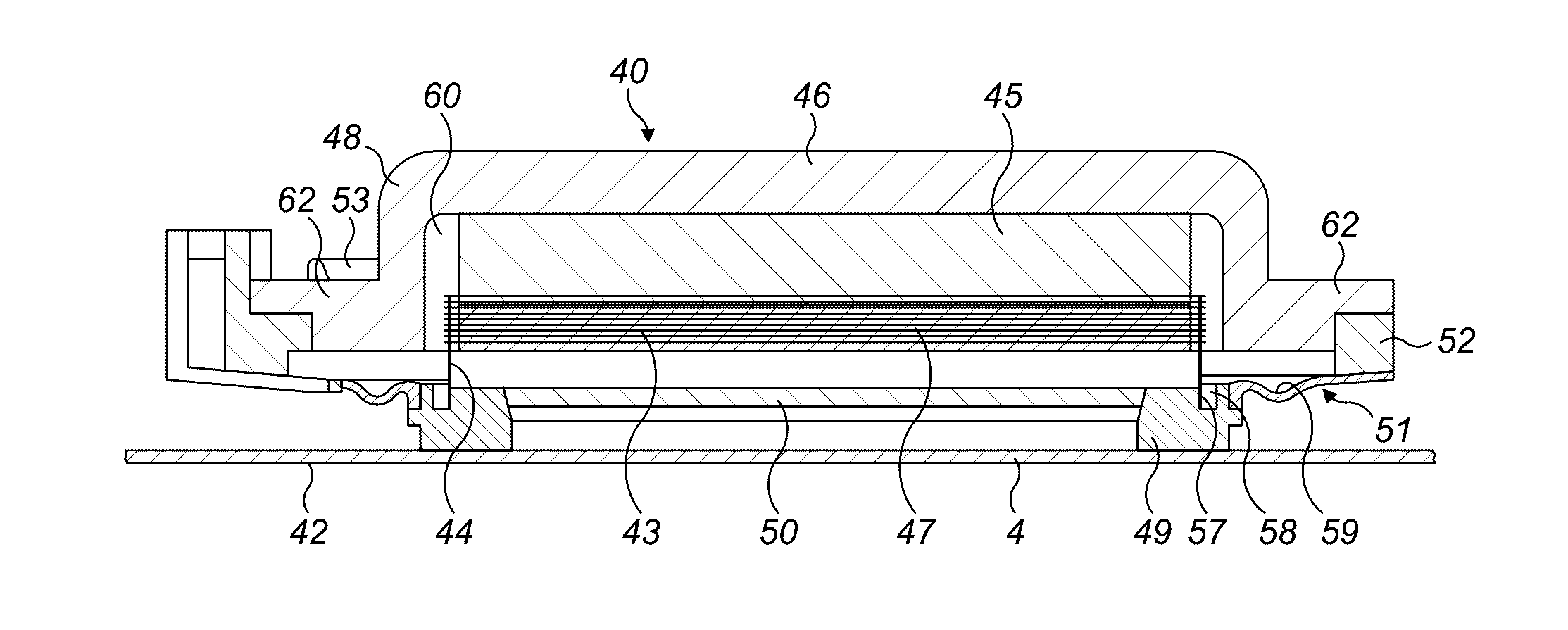
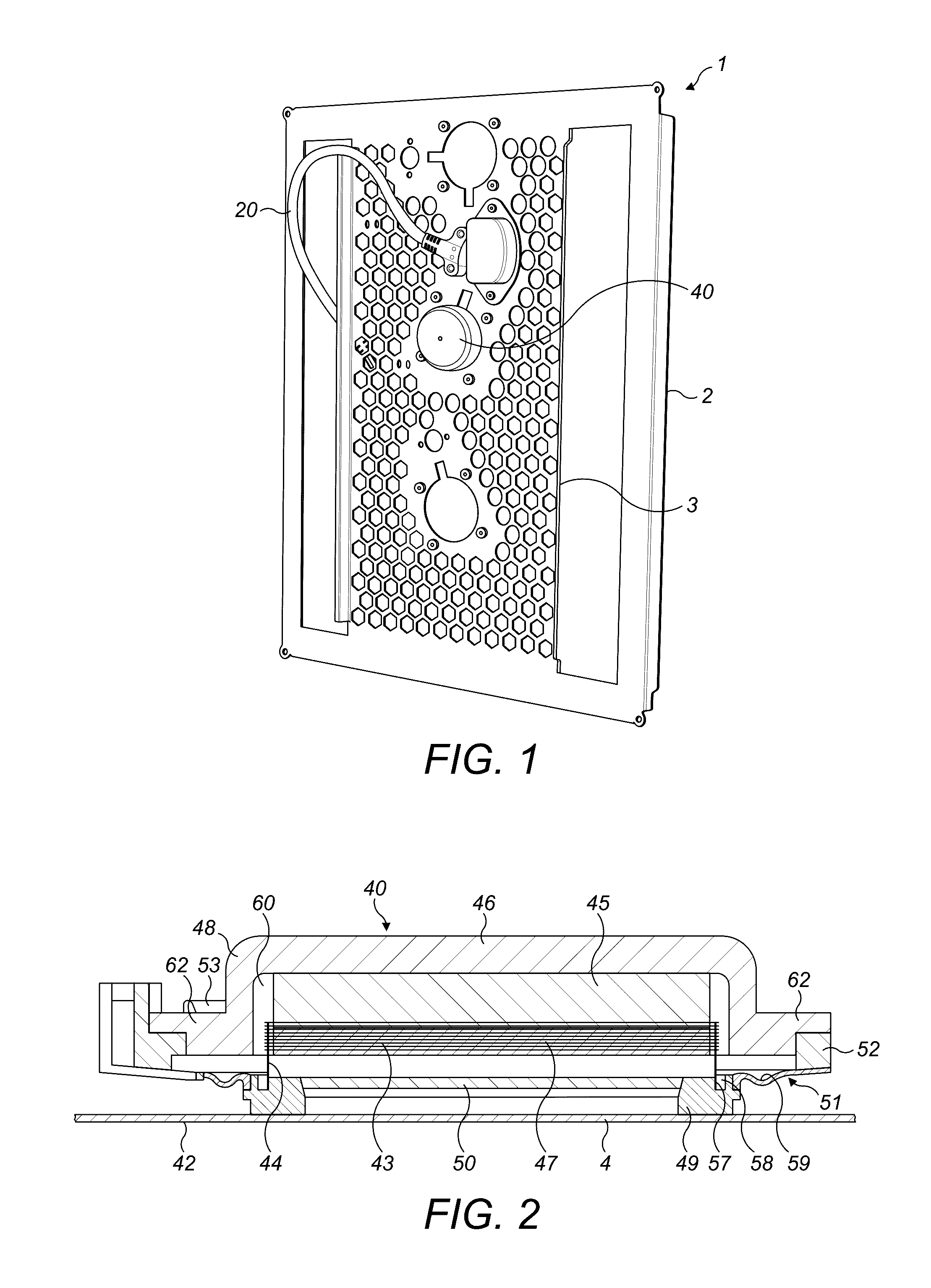
[0039]FIG. 5 is an illustration of a Finite Element Analysis model of one embodiment of a damping member that may be used with a flat panel loudspeaker. FIG. 6 is an illustration of a diagram of a cross section through a flat panel loudspeaker using the damping member shown in FIG. 5. The resonant panel 2 has defined an inner region 7 and an outer region 8. The outer region 8 bounds the inner region 7. The inner region 7 is typically a circular region and substantially corresponds to the central region 4 in FIG. 2. The foot 49 of the exciter 40 has defined therein a series of notches (not shown) which extend from the resonant panel 2 towards the rest of the exciter 40. A damping member 10 is provided on the resonant panel 2. The damping member is an integrally formed part and comprises a plurality of fin sets which extend in a plane perpendicular to a plane of the resonant panel 2 and span the inner region 7. Each fin set intersects the other fin sets at the centre of the inner regi...


PUM


Abstract

There is provided a flat panel loudspeaker comprising a resonant panel, an exciter comprising a foot generally cylindrical in shape, coupled to the resonant panel and defining an inner region of the resonant panel. The exciter is drivable to vibrate the resonant panel via the foot, whereby to produce a sound. A stiffness of the resonant panel in the inner region is greater than a stiffness of the resonant panel in a region of the resonant panel outside the inner region. Additionally or alternatively, the flat panel loudspeaker further comprises a damping member in contact with the inner region of the resonant panel and arranged inside the foot to generally brace against the vibration of the resonant panel so as to damp a response of the resonant panel in the inner region to a vibration from the exciter.

Description

CROSS-REFERENCE TO RLEATED APPLICATIONS[0001]The present invention claims the benefit of priority to Great Britain Patent Application No.1509715.7 filed Jun. 4, 2015 entitled “Distributed mode loudspeaker damping oscillations within exciter feet” the entire content of which is incorporated herein by reference.BACKGROUNDThe Field of the Invention[0002]This invention relates to a distributed mode loudspeaker, in particular a flat panel loudspeaker. A type of driver referred to as an electro-dynamic “exciter”, for example of the type disclosed in international patent application publication number WO98 / 34320 A2, is one that is used as a transducer in, for example, distributed mode vibrating panel loudspeakers to vibrationally excite a resonant flat panel member thereof in response to the exciter being driven by an electrical audio signal. An example of a distributed mode flat panel loudspeaker is shown in FIG. 1.[0003]The distributed mode vibrating panel loudspeaker 1 has a resonant pa...

Claims


Application Information

Patent Timeline
Patent Type & Authority Applications(United States)
IPC IPC(8): H04R1/28H04R9/06
CPCH04R1/2896H04R9/06H04R1/2873H04R7/045H04R2440/05H04R7/24H04R7/26H04R7/04H04R7/06H04R7/10
Inventor MIKALAUSKAS, EGIDIJUS
Owner AMINA TECH
Why Eureka
Try Eureka