
Tendon repair implant and method of implantation

a technology of tendons and implants, applied in the field of orthopaedic implants and methods of treatment, can solve the problems of inability to provide immediate mechanical augmentation of bioinductive implants, damage to rotator cuffs or rotator cuff tendons, and damage to rotator cuffs, and achieve the effect of improving healing and adding strength

Active Publication Date: 2016-12-15
ROTATION MEDICAL
View PDF1 Cites 22 Cited by
  • Summary
  • Abstract
  • Description
  • Claims
  • Application Information

AI Technical Summary

Benefits of technology

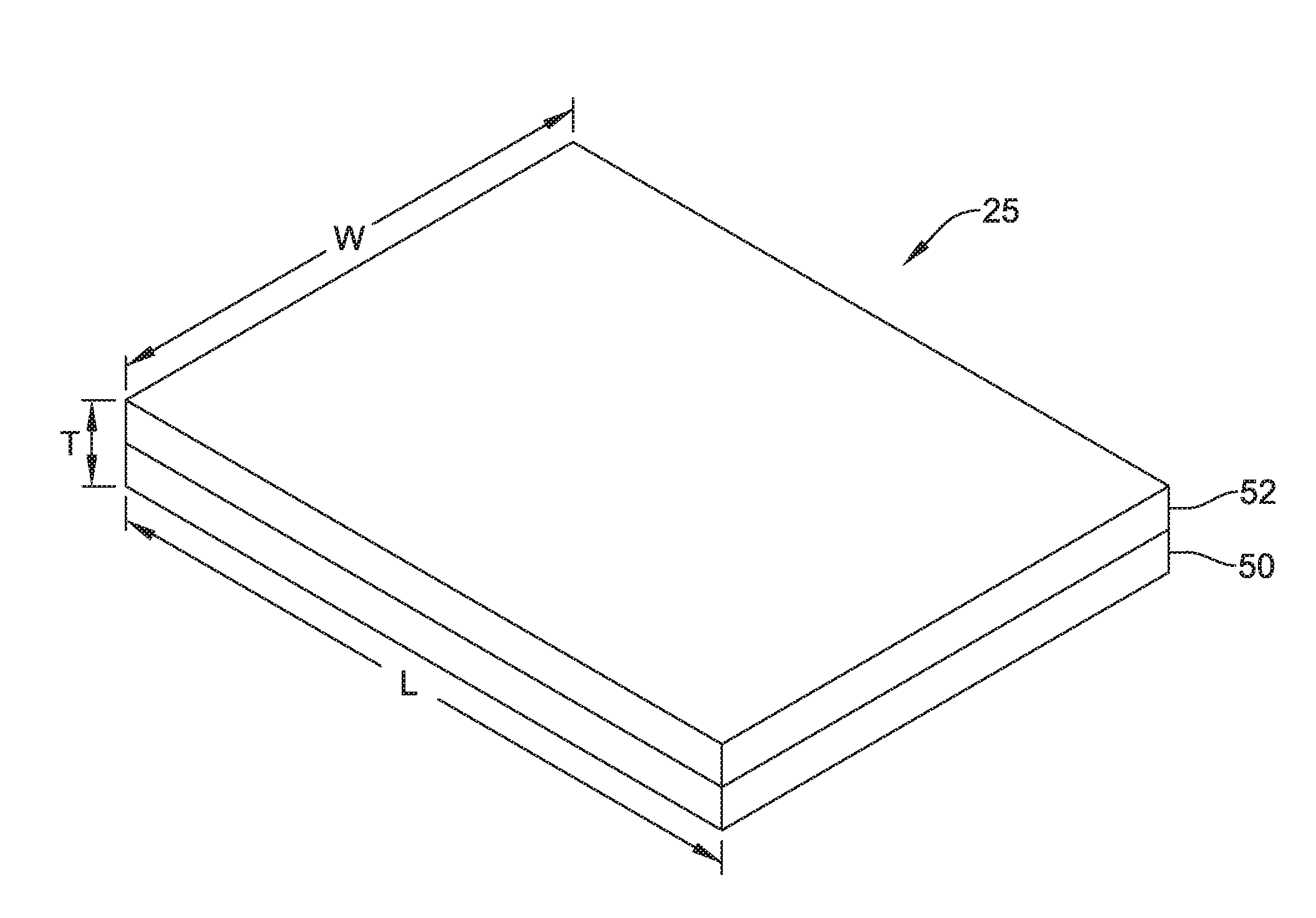
The patent describes a tendon repair implant that combines the benefits of a bioinductive implant and a mechanical augmentation implant. The implant has a sheet-like structure that conforms to the surface of the tendon and is designed to provide initial strength and promote tissue in-growth. The implant has two components that can degrade in strength over time but still maintain their initial load share with the tendon. The implant can be attached to the tendon without significant pre-loading or pre-stretching and has one or more agents to promote tissue in-growth. The sheet-like structure has a maximum of about 0.5% creep over three months and can be designed to degrade in tensile strength or compressive strength. The technical effect of the patent is to provide a tendon repair implant that combines the benefits of a bioinductive and mechanical augmentation implant to promote tissue in-growth and provide initial strength for the tendon.

Problems solved by technology

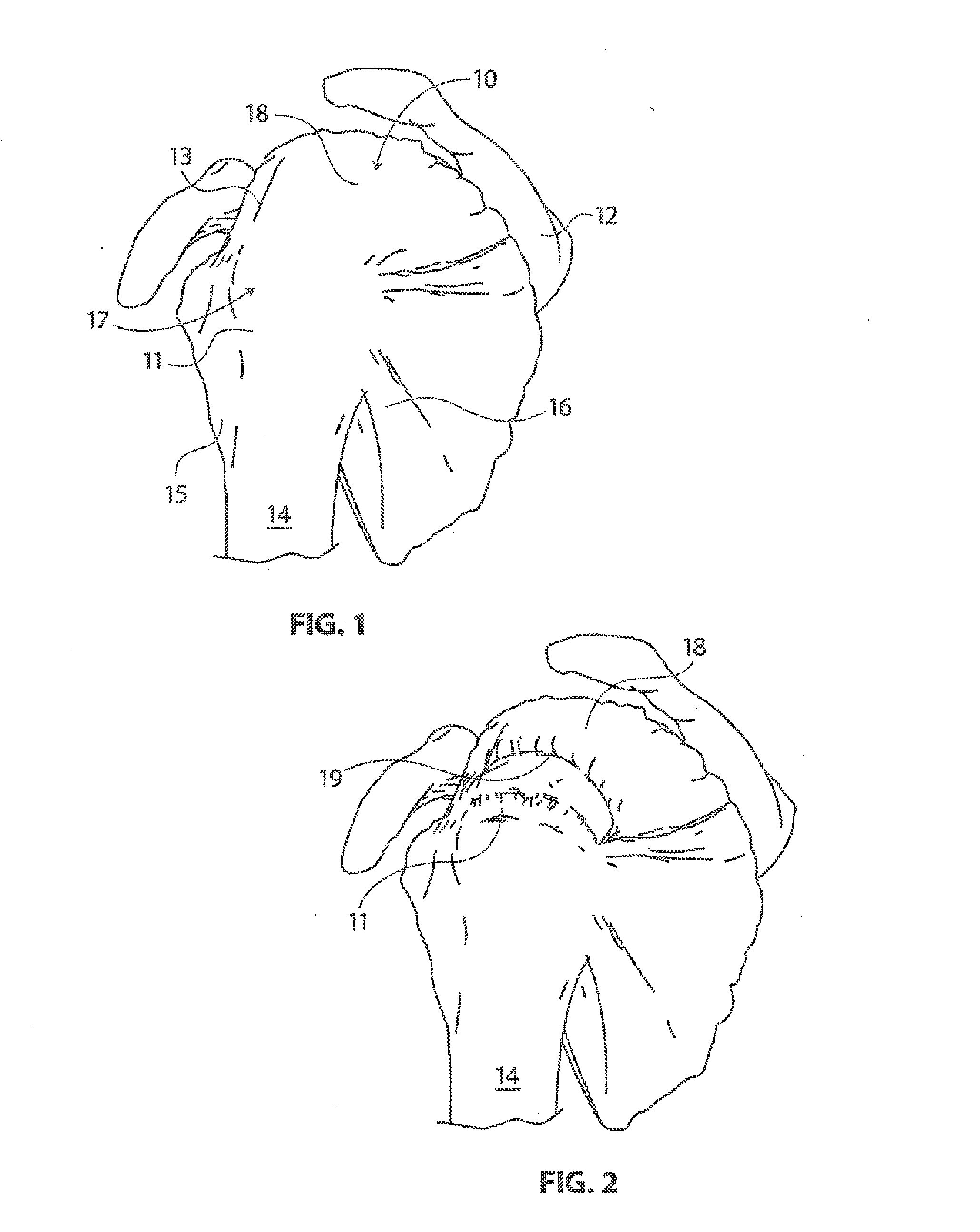
With its complexity, range of motion and extensive use, a common soft tissue injury is damage to the rotator cuff or rotator cuff tendons.
Damage to the rotator cuff is a potentially serious medical condition that may occur during hyperextension, from an acute traumatic tear or from overuse of the joint.
The bioinductive implant, however, does not provide any immediate mechanical augmentation; rather, the newly induced tissue provides biological augmentation over time.
Use of these implants, however, often do not provide any benefit beyond the immediate postoperative period.

Method used


Image

  • Tendon repair implant and method of implantation
  • Tendon repair implant and method of implantation
  • Tendon repair implant and method of implantation

Examples


Embodiment Construction

[0063]The following description should be read with reference to the drawings, which are not necessarily to scale, wherein like reference numerals indicate like elements throughout the several views. The detailed description and drawings are intended to illustrate but not limit the claimed invention. Those skilled in the art will recognize that the various elements described and / or shown may be arranged in various combinations and configurations without departing from the scope of the disclosure. The detailed description and drawings illustrate example embodiments of the claimed invention.

[0064]Definitions of certain terms are provided below and shall be applied, unless a different definition is given in the claims or elsewhere in this specification.

[0065]All numeric values are herein assumed to be modified by the term “about,” whether or not explicitly indicated. The term “about” generally refers to a range of numbers that one of skill in the art would consider equivalent to the re...


PUM

PropertyMeasurementUnit
Lengthaaaaaaaaaa
Lengthaaaaaaaaaa
Fractionaaaaaaaaaa

Abstract

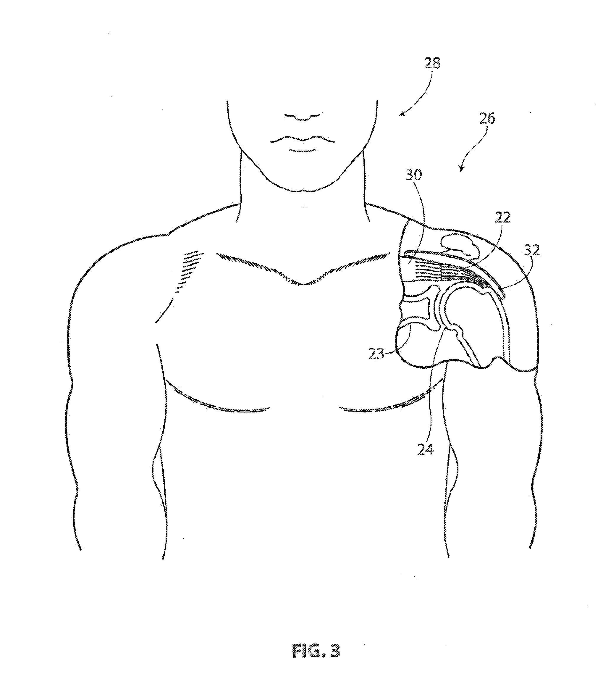
A tendon repair implant for treatment of a complete or partial thickness tear in the supraspinatus tendon of the shoulder is provided. The implant may incorporate features of rapid deployment and fixation by arthroscopic means that compliment current procedures; tensile properties that result in desired sharing of anatomical load between the implant and native tendon during rehabilitation; selected porosity and longitudinal pathways for tissue in-growth; sufficient cyclic straining of the implant in the longitudinal direction to promote remodeling of new tissue to tendon-like tissue; and, may include a bioresorbable construction to provide transfer of additional load to new tendon-like tissue and native tendon over time.

Description

CROSS REFERENCE TO RELATED APPLICATIONS[0001]This application claims the benefit of U.S. Provisional Patent Application Ser. No. 62 / 175,829 filed on Jun. 15, 2015, the disclosure of which is incorporated herein by reference.TECHNICAL FIELD[0002]The present disclosure pertains generally, but not by way of limitation, to orthopedic implants and methods of treatment. More particularly, the present invention relates to a tendon repair implant, such as one that is engineered for arthroscopic placement over or in the area of a full thickness tear of the supraspinatus tendon of the shoulderBACKGROUND[0003]With its complexity, range of motion and extensive use, a common soft tissue injury is damage to the rotator cuff or rotator cuff tendons. Damage to the rotator cuff is a potentially serious medical condition that may occur during hyperextension, from an acute traumatic tear or from overuse of the joint. The accepted treatment for a full thickness rotator cuff tear includes reattaching th...

Claims


Application Information

Patent Timeline
IPC IPC(8): A61F2/08A61F2/00
CPCA61F2/08A61F2210/0004A61F2210/0076A61F2/0063A61F2250/0017A61F2250/0018A61F2250/0023A61F2250/003
Inventor VAN KAMPEN, CRAIG
Owner ROTATION MEDICAL
Learn More