Creation of slots on the surface of a core

Inactive Publication Date: 2016-12-15
MONTUPET
View PDF0 Cites 0 Cited by
  • Summary
  • Abstract
  • Description
  • Claims
  • Application Information

AI Technical Summary

Benefits of technology

The invention proposes a foundry core for casting aluminium alloy in a mold. The core has a molding part in contact with the melted metal and non-molding parts outside the mold. The non-molding parts are the core prints that keep the core in position within the mold. The non-molding parts also have slots on their surface with a width and depth designed to discharge gases generated during casting. The slots are created using laser or tooling with reliefs in the shape of blades. The invention also provides a mold with a suction system to suction in the generated gases, and a method for manufacturing the core by etching the slots on its surface using a laser. The technical effect of the invention is to provide a more efficient and effective means for casting aluminum alloy in a mold, reducing the amount of gas generated during casting and improving the quality of the casted pieces.

Problems solved by technology

This defect embrittles the piece and compromises its qualities.
Even if the bubbles manage to exit from the cast piece, gas discharges can leave traces of their passage in the solidified metal and are potentially responsible of porous aluminium sheet or even a priming zone for crack propagation.
But this technique embrittles the cores due to decrease in the number of resin bridges between the grains.
Also, the use of large grains for the cores also changes the surface state of the piece to the point where the roughness measured on the surfaces of the piece can compromise their quality.
Finally, this solution involves managing several sizes of grains of sand in a factory, which constitutes an additional inconvenience.
This configuration is delicate to carry out and its configuration needs permanent control which constitutes a disadvantage per se.
Also, the shape of the cores is often poorly adapted to their use.
Their management and their maintenance represent complications of a technical and economic order.
It appears that the different attempts at resolving the problem of gaseous discharge of cores are all exposed to limitations.

Method used


Image

  • Creation of slots on the surface of a core
  • Creation of slots on the surface of a core
  • Creation of slots on the surface of a core

Examples


Embodiment Construction

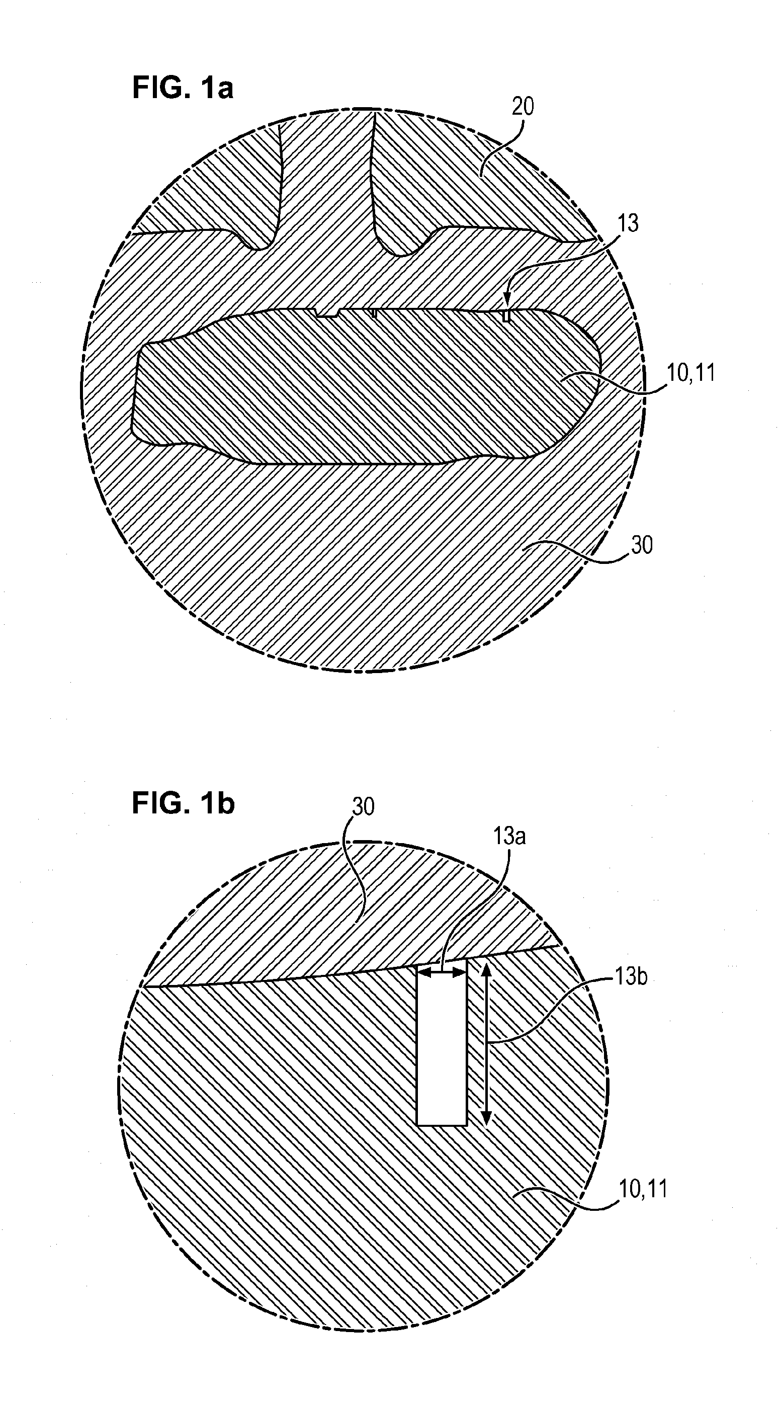
[0046]In relation to FIGS. 1a, 1b, 2a, 2b, 3a, 3b a core 10 as per the invention is described.

[0047]The core 10 is adapted for casting foundry pieces in a mold 20. These cast foundry pieces are made of aluminium alloy and are typically intended for the automobile industry. These cast pieces are typically intended to be engine blocks or cylinder heads.

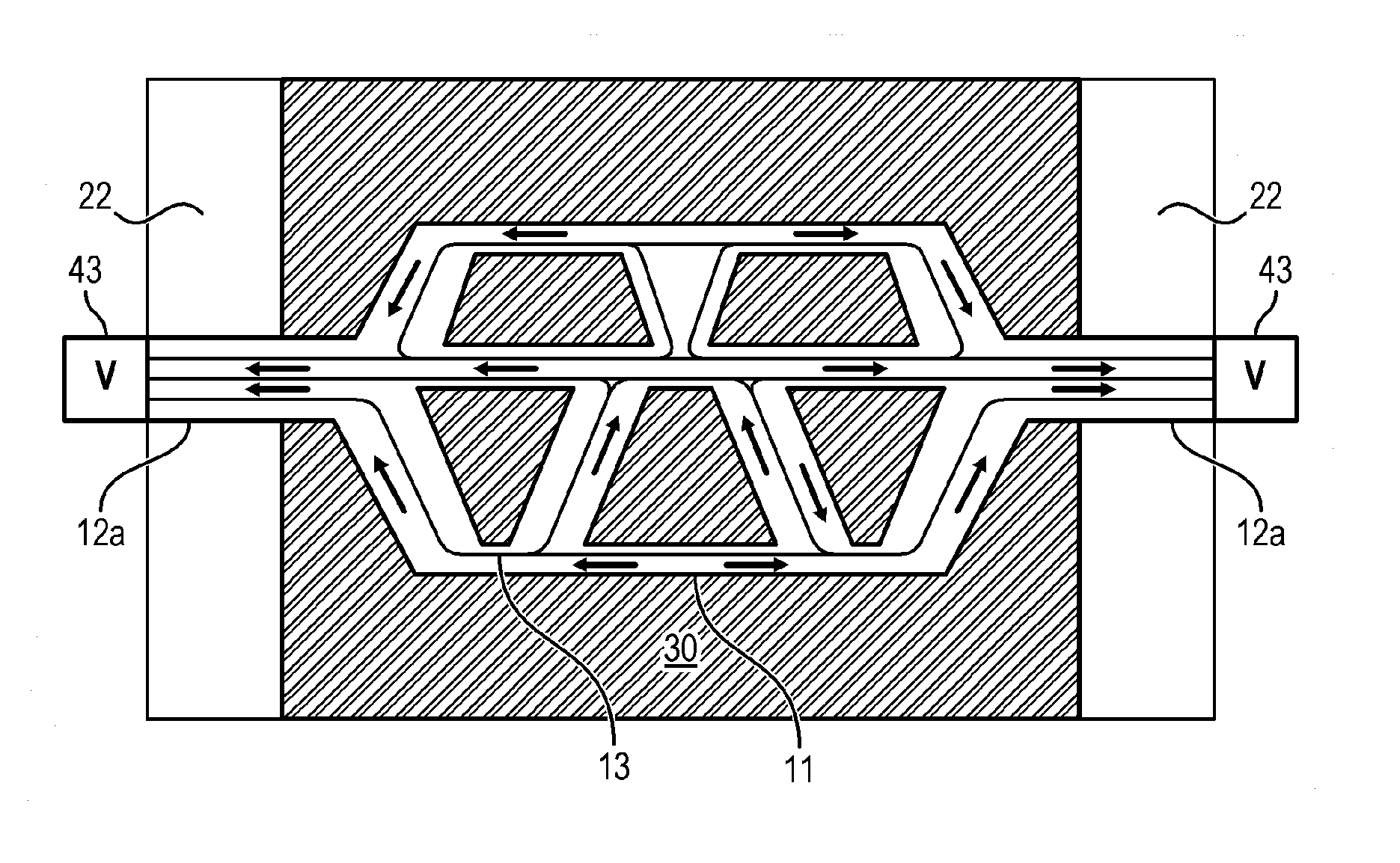
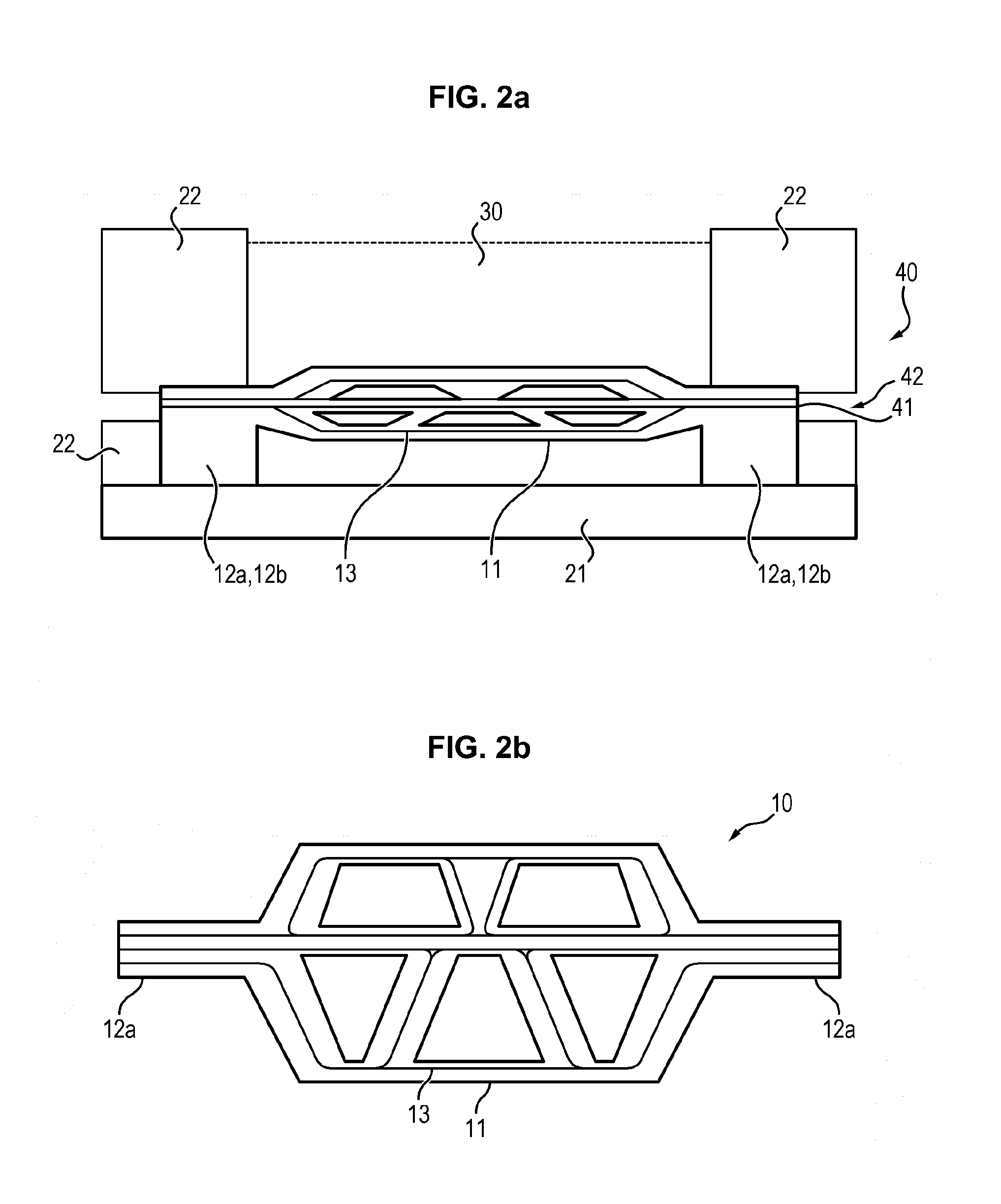
[0048]The core 10 comprises a molding part 11 which is intended to be in contact with the molten aluminium alloy 30.

[0049]The core 10 also comprises a non-molding part 12a, intended to be located outside the molten aluminium alloy 30. In general, a core 10 comprises several non-molding parts 12a separated especially by the molding part 11.

[0050]The core 10 is placed inside the mold 20 and held there immobile by the core prints 12b, which are generally non-molding parts 12a (see FIG. 2a). Generally, the mold 20 comprises a sole 21 which constitutes the bottom of the mold 20, and at least one movable guillotine 22 which constitutes a side...


PUM

PropertyMeasurementUnit
Widthaaaaaaaaaa
Widthaaaaaaaaaa
Depthaaaaaaaaaa

Abstract

The invention relates to a foundry core for cast pieces of aluminium alloy in a mold, said core comprising a molding part, intended to be in contact with the molten aluminium alloy, and at least one non-molding part intended to be located outside the molten aluminium alloy, the core comprising at least one slot on the surface of the core, said slot extending from the molding part to at least one non-molding part for discharge of the gases generated in the molding part of the core during casting outside the molding part.

Description

FIELD OF THE INVENTION[0001]The present invention relates to the field of foundry and casting of foundry pieces in aluminium alloy.[0002]The invention relates more particularly to a foundry core for casting pieces in aluminium alloy in a mold. The relevant cores especially include a mixture of sand and binder.TECHNOLOGICAL BACKGROUND[0003]The foundry core constitutes part of the mold serving to produce a piece made of metal and in particular aluminium alloy.[0004]The core is generally composed of a mixture of grains of sand and binder.[0005]The foundry core enables creation of internal recesses of a piece. It is therefore immersed fully or partly in the molten metal.[0006]When a core is enclosed by molten aluminium alloy, the phenomena of dilation of air, evaporation of the solvents of the binders and their combustion linked to the rise in temperature will boost the pressure in the core. This rise in pressure is accompanied by generation of gases inside the core. The resulting gases...

Claims


Application Information

Patent Timeline
IPC IPC(8): B22C9/10B22C9/24
CPCB22C9/24B22C9/106B22C9/067B22D21/04F02F1/24F02F7/00F02F2200/06
Inventor MORLOT, VINCENT
Owner MONTUPET
Why Eureka
Try Eureka