

Vented clothes dryer with passive heat recovery
a technology of passive heat recovery and clothes dryer, which is applied in the direction of drying machines, drying, light and heating equipment, etc., can solve the problems of difficult to ensure that the intake air b>100/b> passes, and achieve the effect of reducing the total energy consumption of a drying cycl
- Summary
- Abstract
- Description
- Claims
- Application Information
AI Technical Summary
Benefits of technology
Problems solved by technology
Method used
Image

Examples
second embodiment
[0035]To reduce the need to have good sealing of the cabinet 115, which is necessary to create an overall negative pressure within the cabinet 115, the present invention has an additional fan 113 as presented in FIG. 7. This fan 113 may be added to pull the intake air through the heat exchanger 105 (hidden by fan). This fan 113 may require a fan shroud to create a negative pressure between the heat exchanger 105 and the fan 113. In this arrangement, the fan 113 may be sized to match the airflow provided by the blower 103, as to keep the pressure within the cabinet 115 nearly neutral with respect to the external pressure surrounding the cabinet 115. Since the airflow through the blower 103 is dependent on items such as the external exhaust duct length and number of turns in this duct, as well as the content of the load within the drum 102, it is likely that the pressure within the cabinet 115 will vary from slightly negative to slightly positive. Since the heat exchanger 105 is locat...
third embodiment
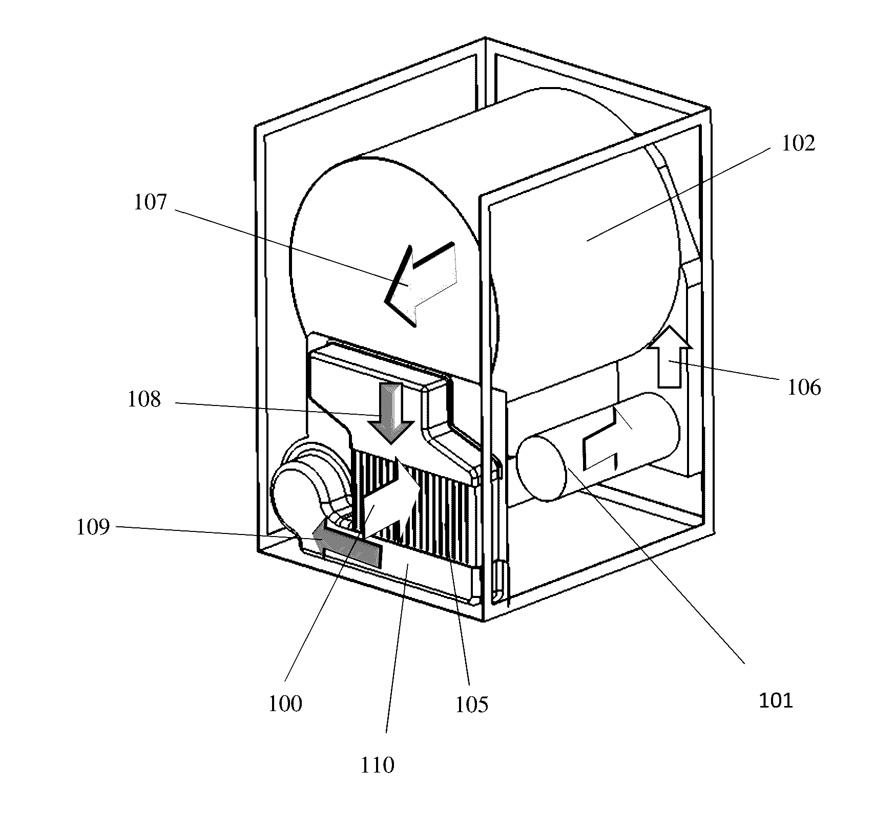
[0036]As an alternative to the addition of a fan 113, the airflow 111 between the heat exchanger 105 and the heating tube 101 can be guided by a duct 114 in another embodiment of the present invention. An isometric view of this implementation from the rear of the dryer is presented in FIG. 8. A cross-sectional view of the ducted airflow pattern is also presented in FIG. 9. The intake air 100 passes through the heat exchanger 105, and that same airstream 111 leaves the heat exchanger through a duct 114 and enters the heating tube 101. The hot air 106 leaving the heating tube 101 then enters the drum 102. The airflow 107 within the drum 102 cools as it picks up moistures from the contents (not shown) within the drum 102. The warm humid air 108 then passes through the heat exchanger 105, where it exchanges heat with the intake air 100. The warm, humid air 109 leaving the heat exchanger 105, is pulled through the blower 103, and then exhausts 104 from the dryer. In the third embodiment,...
fourth embodiment
[0038]In an additional set of embodiments, the heat exchanger 105 can be integrated, via ducting, to the drum intake ducting 116, which receives intake air 100 after preheating. The heat exchanger 105, is connected to the blower 103 exhaust ducting 118, as represented in FIG. 10. In this, fourth embodiment, the drum 102 exhaust is directly ducted 117 to the blower (not shown) intake, as is typically done with conventional tumble dryers. A cross sectional view of this embodiment is presented in FIG. 11. In this view, the flow path 123 of the intake air 100 as it collects heat from the warm humid exhaust air 121 leaving the blower is presented. In this embodiment, preheated air 111 passes through a booster fan 120 which helps overcome the pressure loss from the heat exchanger 105. The intake air flow path 123 is longer than the exhaust air flow path 124 inside the heat exchanger 105. In this configuration, the intake air 100 has a larger pressure loss to overcome than the exhaust air ...
PUM
 Abstract
Description
Claims
Application Information