
Circulating Resampling Digitizer

Inactive Publication Date: 2016-12-15
TEKTRONIX INC
View PDF5 Cites 5 Cited by
  • Summary
  • Abstract
  • Description
  • Claims
  • Application Information

AI Technical Summary

Benefits of technology

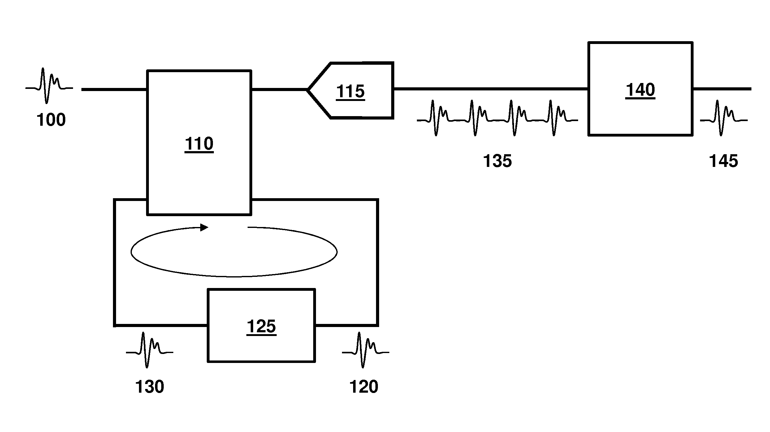
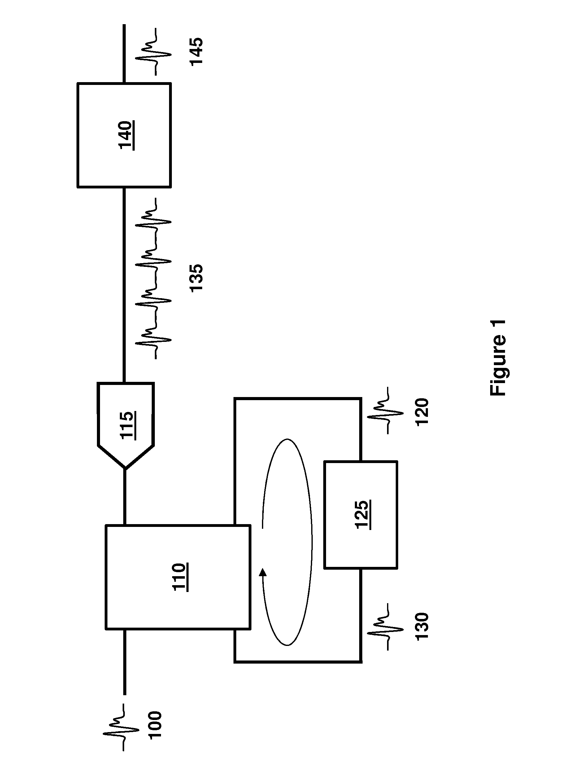
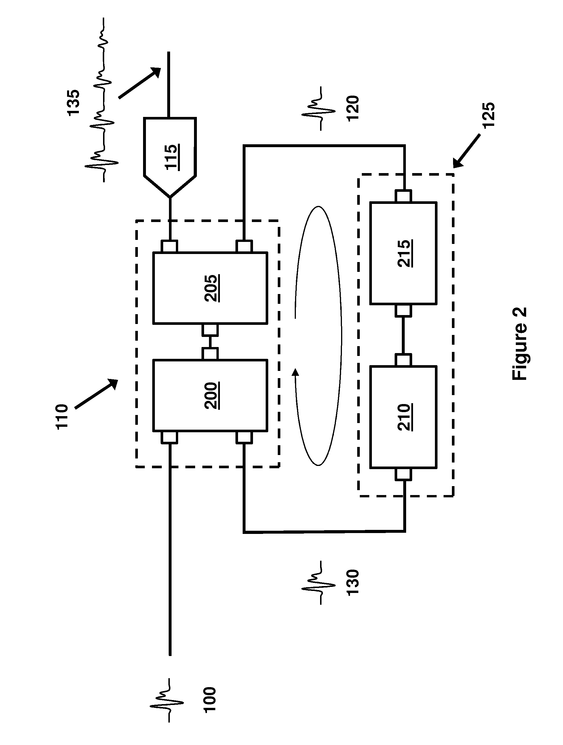
The present invention provides better ways to sample and reconstruct signals using digital instruments. A new circuit called a circulating resampling digitizer (CRD) is described that makes multiple copies of an input signal and samples one of them while sending the other through a delay loop. This allows the CRD to keep sampling the same event multiple times, resulting in a cleaner representation of the original signal with more detail and at a higher sample rate.

Problems solved by technology

The digitizer often limits the accuracy with which the signal can be captured.
For example, the digitizer's sampling rate creates an upper limit on the signal frequencies that can be captured.
The number of bits used in the digitizer limits the instrument's vertical resolution.
The digitizer also adds some noise to the signal.
Due to their nature, sampling oscilloscopes can only process repetitive signals.
None of the prior art, however, has combined a circulating delay with a real-time oscilloscope.

Method used


Image

  • Circulating Resampling Digitizer
  • Circulating Resampling Digitizer
  • Circulating Resampling Digitizer

Examples


Embodiment Construction

[0019]As signal speeds increase, there is an ever-growing need for faster and more accurate instruments. Digitizers commonly create limits on a digital instrument's sample rate and vertical resolution, and add digitizer noise. Typically, these have been improved by using a digitizer with a faster sampling rate, more bits of resolution, or lower noise. But improved digitizers cannot be easily installed in older instruments. And even the best digitizers used in new instruments will still have sampling rate, resolution, and noise limitations. Thus, there is a need for improved sampling techniques that will enhance the instrument's sampling rate and vertical resolution while decreasing digitizer noise. Ideally, these techniques could be implemented by existing instruments without expensive modifications. Accordingly, embodiments of the present invention provide circuits and methods for a circulating resampling digitizer (“CRD”) and associated signal reconstruction.

[0020]In one embodimen...


PUM


Abstract

Embodiments of the present invention provide improved techniques for sampling events in electrical test equipment such as real-time oscilloscopes. A circulating resampling digitizer uses a delay loop to repeatedly acquire replicas of an input event. The replicas are used to create a series of events which may be output or stored in memory. Signal reconstruction techniques such as interleaving and / or averaging may be applied to the series in order to construct a digital representation of the original input event. The resulting representation may have a higher sample rate, lower noise, and higher vertical resolution than each event in the series. The disclosed techniques use low cost components and can be added to existing instruments with little or no modification.

Description

FIELD OF THE INVENTION[0001]The present invention relates to techniques for improving sample rate, noise, and bits of resolution in electrical test and measurement instruments.BACKGROUND OF THE INVENTION[0002]Digital instruments such as real-time oscilloscopes use an analog-to-digital converter (“digitizer”) to create a digital representation of an electrical input signal. The digitizer often limits the accuracy with which the signal can be captured. For example, the digitizer's sampling rate creates an upper limit on the signal frequencies that can be captured. The number of bits used in the digitizer limits the instrument's vertical resolution. The digitizer also adds some noise to the signal. In order to improve instrument accuracy, there is a need for improved sampling techniques that can increase the sample rate and vertical resolution of an instrument, while reducing noise.[0003]Circulating delays have previously been used in optical instruments that do not operate in real tim...

Claims


Application Information

Patent Timeline
IPC IPC(8): H03M1/06H03K3/86G01R13/02H03M1/12
CPCH03M1/0626G01R13/0272H03K3/86H03M1/121G01R13/0209
Inventor PICKERD, JOHN P.
Owner TEKTRONIX INC
Learn More