
Means for alleviating strain on a wind turbine rotor blade

Active Publication Date: 2016-12-22
SIEMENS GAMESA RENEWABLE ENERGY AS
View PDF9 Cites 4 Cited by
  • Summary
  • Abstract
  • Description
  • Claims
  • Application Information

AI Technical Summary

Benefits of technology

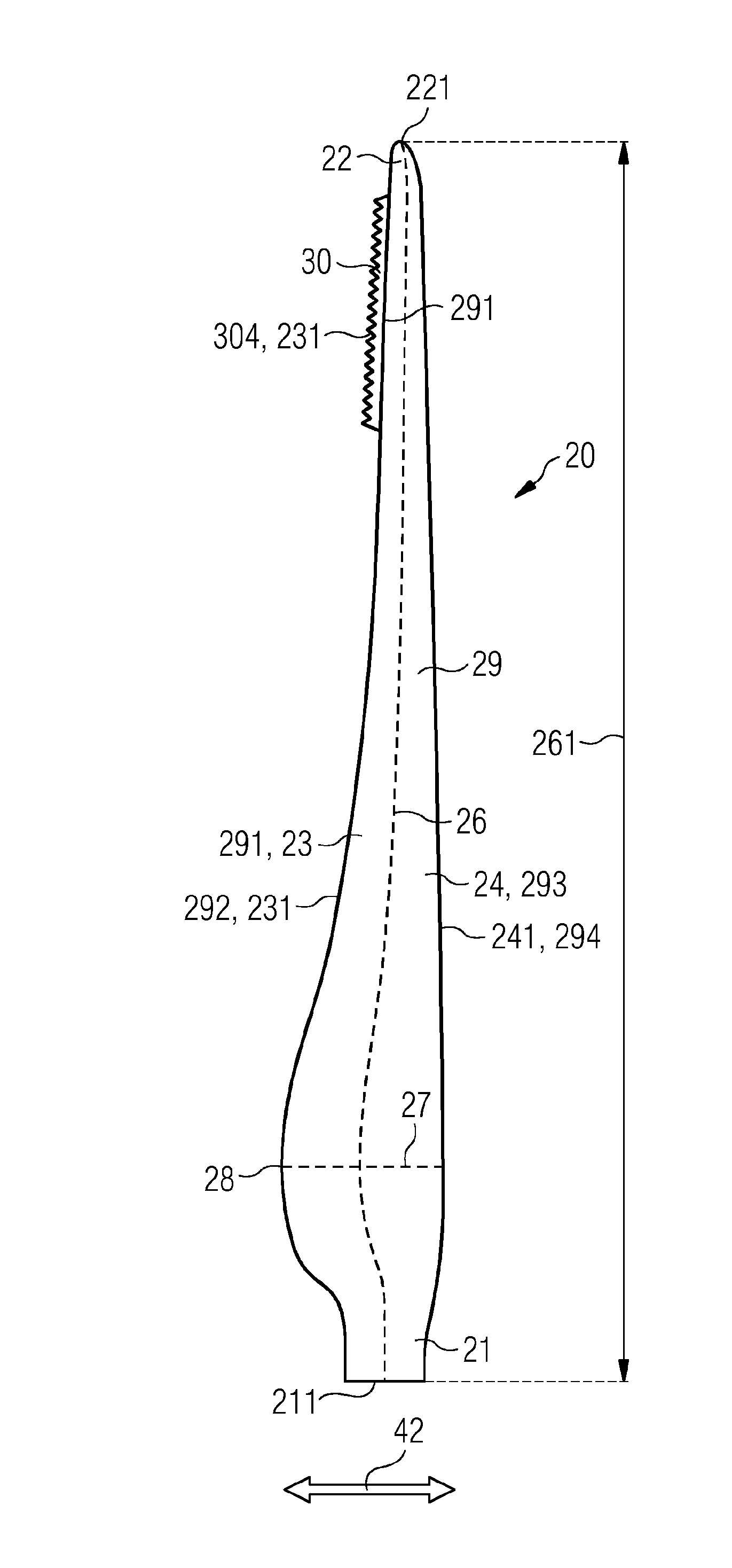
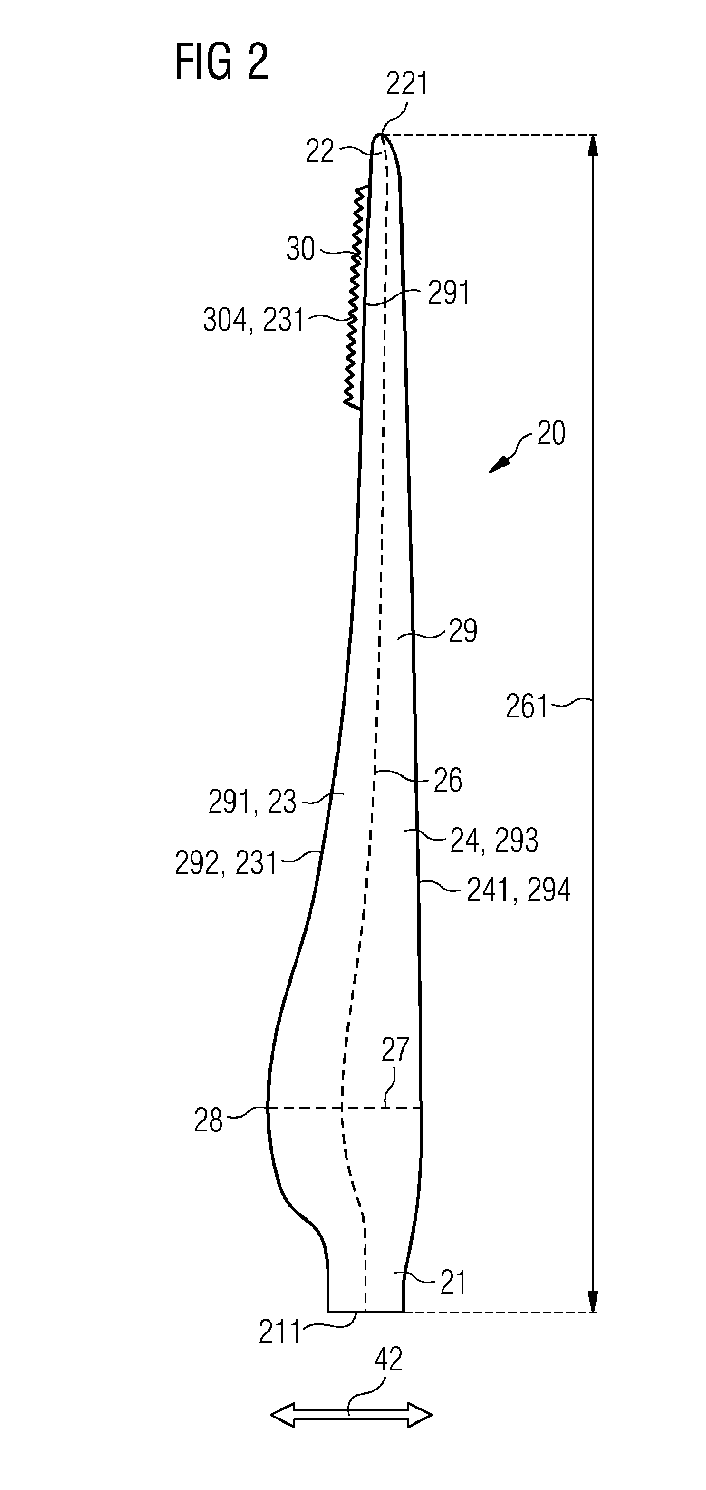
The patent describes a connection design for a wind turbine blade and an aerodynamic device, such as a flap, that improves the aerodynamic properties by reducing vortices and eddies at the interface between them. The connection design includes two parts that are connected closely to each other, with the first part acting as a connection member and the second part as the aerodynamic device. This design allows for a smooth transition between the main body and the aerodynamic device and ensures the aerodynamic properties are optimized. Additionally, the design allows for the aerodynamic device to be manufactured and provided as in the state of the art, with only the connection to the remaining rotor blade needing to be re-designed by incorporating the buckling properties.

Problems solved by technology

However, such an actuation and control system as it is known from airplanes has the drawbacks of relatively high costs, high durability requirements and the difficulty of access for servicing the system.
A disadvantage of the proposed passive adaptive structures is that it requires significant changes and re-design of the rotor blade.
Thus, it is not possible to retrofit existing rotor blades by the proposed concept.
Furthermore, also the design of a new rotor blade implementing the proposed concept seems to imply considerable costs and efforts.
Thus, apart from the stability limit, there also exists an elasticity limit of the buckling section.
Obviously, at certain forces acting on the aerodynamic device even these sections of the aerodynamic device may deform and ultimately break, thus are not rigid anymore.

Method used


Image

  • Means for alleviating strain on a wind turbine rotor blade
  • Means for alleviating strain on a wind turbine rotor blade
  • Means for alleviating strain on a wind turbine rotor blade

Examples


first embodiment

[0114]The first embodiment is shaped as in a U-shape. In other words, it comprises a plane and two stabilizers, namely a stabilizer 39 and a further stabilizer 391, the two stabilizers 39, 391 being arranged perpendicularly to the plane.

[0115]In can be seen in FIG. 6 that, if a force is applied in flapwise direction on the aerodynamic device, a bending moment 55 results, and the aerodynamic device 30 deforms. Deformation of the aerodynamic device 30 takes place at both the planar section and the stabilizers 39, 391. As a result, the aerodynamic device 30 is bent upwards and will thus influence the aerodynamic properties of the rotor blade in the desired manner. In particular, lift of the rotor blade may be reduced. Note that the deformation is reversible and that it occurs completely passively.

second embodiment

[0116]FIGS. 7 and 8 show the invention. They show another aerodynamic device 30 with an attachment section 31 comprising a device leading edge section 301, and a buckling section 32 and an aerodynamic section 33. The aerodynamic section 33 comprises a device trailing edge section 302 and comprises a plurality of serrations 38. The purpose of the serrations 38 is mainly the reduction of noise that is generated during rotation of the rotor blade about the rotor axis of rotation.

[0117]In the example of FIG. 7, the aerodynamic device is arranged and prepared for being attached at the pressure side of a main body of a rotor blade at the trailing edge section. Furthermore, it is arranged and prepared that a force component 51 is acting on the aerodynamic device 30 such that if the force component 51 reaches the stability limit of the buckling section 32, the aerodynamic section 33 and also, at least partly, the buckling section 32 bend upwards towards the suction side of the rotor blade d...

third embodiment

[0119]FIGS. 10 and 11 show an aerodynamic device 30 comprising an attachment section 31, a buckling section 32 and an aerodynamic section 33. Again, the aerodynamic section 33 comprises a plurality of serrations 38 for reducing noise that is generated by the rotor blade of the wind turbine. Also similarly to the embodiment as shown in FIGS. 7 to 9, the aerodynamic device 30 comprises a stabilizer 39 and a further stabilizer 391 for reducing the deformation of the aerodynamic device 30 in substantially flapwise direction for forces being smaller than the stability limit of the buckling section 32. In the embodiment as shown in FIG. 10, the buckling element 32 comprises a corrugation 37. Thus, a corrugated hinge element is obtained. This has the advantage that deformation of the buckling element 32 is facilitated as can be seen in FIG. 11. This has the effect that contrary to the previous embodiment as shown in FIGS. 7 to 9, where the stabilizer 39 is bent and twisted upon deformation...


PUM


Abstract

A rotor blade for a wind turbine with an aerodynamic device, and an aerodynamic device is provided. The rotor blade includes a main body defining a pressure side and a suction side of the rotor blade, and includes a main body trailing edge section. The rotor blade includes an aerodynamic device with an attachment section for attaching the aerodynamic device to the main body trailing edge section, an aerodynamic section for influencing the aerodynamic properties of the rotor blade, and a buckling section for controlling the orientation and / or the shape of the aerodynamic section with regard to the main body. The aerodynamic device is configured such that it deforms elastically for a force component acting in flapwise direction on the buckling section, and deforms abruptly if a force component of about the size of the stability limit of the buckling section acts in flapwise direction on the buckling section.

Description

CROSS-REFERENCE TO RELATED APPLICATIONS[0001]This application claims priority to PCT Application No. PCT / EP2015 / 051259, having a filing date of Jan. 22, 2015, based off of European application No. EP 14154895.8 having a filing date of Feb. 12, 2014, the entire contents of which are hereby incorporated by reference.FIELD OF TECHNOLOGY[0002]The following relates to a rotor blade for a wind turbine comprising an aerodynamic device for influencing the aerodynamic properties of the rotor blade. Furthermore, the following relates to the aerodynamic device of such a rotor blade.BACKGROUND[0003]A mechanism to reduce extreme loads, which may be caused by events such as gusts, overspeed, emergency stops or the like, is desirable for wind turbines. It is advantageous to reduce extreme loads, as this potentially increases lifetime and durability of the wind turbine. A beneficial consequence of preventing, or at least mitigating, the occurrence and the impact of extreme loads is that this would ...

Claims


Application Information

Patent Timeline
IPC IPC(8): F03D7/02F03D1/06
CPCF03D7/0236F03D7/0296F03D1/0641F03D1/0683F05B2240/311Y02E10/72F05B2240/305F03D1/0675
Inventor GONZALEZ, ALEJANDRO GOMEZLOEVEN, ALEXTORGARD, SIGMUND WENNINGSTED
Owner SIEMENS GAMESA RENEWABLE ENERGY AS
Learn More