Gas sensor

a technology of gas sensor and inner tube, which is applied in the field of gas sensor, can solve the problems of sensor element or tubular member breakage, insufficient gas tightness, and shorter axial length of the filled sealing member, and achieve the effect of gas tightness, easy spreadability, and gas tightness

Active Publication Date: 2016-12-22
NGK INSULATORS LTD
View PDF3 Cites 5 Cited by
  • Summary
  • Abstract
  • Description
  • Claims
  • Application Information

AI Technical Summary

Benefits of technology

[0046]For example, while the inner tube 43 has the diameter contracted portion 43c in the above-described embodiment, the diameter contracted portion 43c may be omitted. Furthermore, the size of the inner tube 43 in the axial direction may be shorter than that in FIG. 1. FIG. 3 is a vertical sectional view of a gas sensor 210 according to a modification in such a case. FIG. 3 illustrates only an element enclosing member 241 and the sensor element 20 among components of the gas sensor 210. In the element enclosing member 241, as illustrated in FIG. 3, a length of an inner tube 243 in the axial direction is shorter than that of the inner tube 43 in FIG. 1. Moreover, the diameter contracted portions 43c and 43d and the gradually expanding portion 43b are not formed in the inner tube 243. Instead, an opening end at the base end side (upper end in FIG. 3) of the inner tube 243 is bent to form a diameter contracted portion 243b. The supporter 44a, the powder compact 45a, a supporter 244b, a powder compact 245b, the supporter 44c, and the metal ring 46 are successively arranged in the mentioned order between the bottom surface 42d of the main hardware 42 and the diameter contracted portion 243b. The supporter 244b and the powder compact 245b have shorter lengths in the axial direction than the supporter 44b and the powder compact 45b illustrated in FIG. 1, respectively. Similar advantageous effects to those in the above-described embodiment are also obtained with the gas sensor 210. For example, by setting the arithmetic average roughness Ra of the inner peripheral surface 42c to be 0.5 to 5 μm, the gas tightness between the main hardware 42 and the sensor element 20 is relatively improved. When the length of the element enclosing member 241 in the axial direction is shortened, for example, by shortening the length of the inner tube 43 in the axial direction, the gas tightness tends to reduce. However, since the gas tightness is improved by setting the arithmetic average roughness Ra of the inner peripheral surface 42c to be 0.5 to 5 μm, the eventual gas tightness can be avoided from being reduced as a result of the above-mentioned improvement in the gas tightness. Stated in another way, even when a length of the gas sensor in the axial direction is shortened in comparison with that of a gas sensor in which the arithmetic average roughness Ra of the inner peripheral surface 42c is not in the range of 0.5 to 5 μm, the gas tightness can be held at the same level. Thus, the size of the gas sensor 210 can be reduced. While, in the gas sensor210 of FIG. 3, the length of the inner tube 243 in the axial direction is shorter than that of the inner tube 43 in FIG. 1, the length of the main hardware 42 in the axial direction may be shortened instead.
[0047]In the gas sensor 210 of FIG. 3, the supporter 244b may be dispensed with. FIG. 4 is a vertical sectional view of a gas sensor 310 according to another modification in such a case. In an element enclosing member 341 of the gas sensor 310, a powder compact 345a is pressed from above and below in a state sandwiched between the supporter 44a and the supporter 44c. Similar advantageous effects to those in the above-described embodiment are also obtained with the gas sensor 310. It is to be noted that, in FIG. 4, the main hardware 42 and the inner tube 243 are formed integrally with each other, as seen from the drawing.
[0048]While, in the above-described embodiment, the arithmetic average roughness Ra is set to 0.5 to 5 μm over the entire inner peripheral surface 42c of the main hardware 42, the arithmetic average roughness Ra is just required to be 0.5 to 5 μm at least in a region where the inner peripheral surface 42c is contacted with the powder compact 45a.
[0049]In the above-described embodiment, the inner peripheral surface of the inner tube 43 may be formed to have the arithmetic average roughness Ra of 0.5 to 5 μm. With that feature, the void space generated between the powder compact 45b and the inner peripheral surface of the inner tube 43 is reduced, whereby the gas tightness between the inner tube 43 and the sensor element20 is further improved.
[0050]In the above-described embodiment, when, among the surfaces of the supporter 44a, at least the surface (upper surface in FIG. 1) pressing the powder compact 45a has the arithmetic average roughness Ra of not more than 0.5 μm, the advantageous effect of making the powder compact 45a more easily spreadable in the radial direction is obtained as in the above-described embodiment. That point is similarly applied to the supporter 44b.
[0051]In the above-described embodiment, the surface of the sensor element 20 may be formed to have the arithmetic average roughness Ra of 0.5 to 5 μm. With that feature, because the arithmetic average roughness Ra is not less than 0.5 μm, a contact area between each of the powder compacts 45a and 45b and the sensor element 20 is increased, and because the arithmetic average roughness Ra is not more than 5 μm, the powder compacts 45a and 45b can be sufficiently filled into valley portions (recesses) of the surface of the sensor element 20. Therefore, the gas tightness between each of the main hardware 42 and the inner tube 43 and the sensor element 20 is further improved.

Problems solved by technology

With the further reduction in size, however, an axial length of the filled sealing member becomes shorter, and the gas tightness is more apt to be insufficient.
While the gas tightness can be enhanced by increasing a sealing pressure (sealing load) applied to the sealing material, an excessive increase of the sealing pressure may cause the problem, for example, that the sensor element or the tubular member is broken.

Method used


Image

  • Gas sensor
  • Gas sensor
  • Gas sensor

Examples


experimental examples 1 to 7

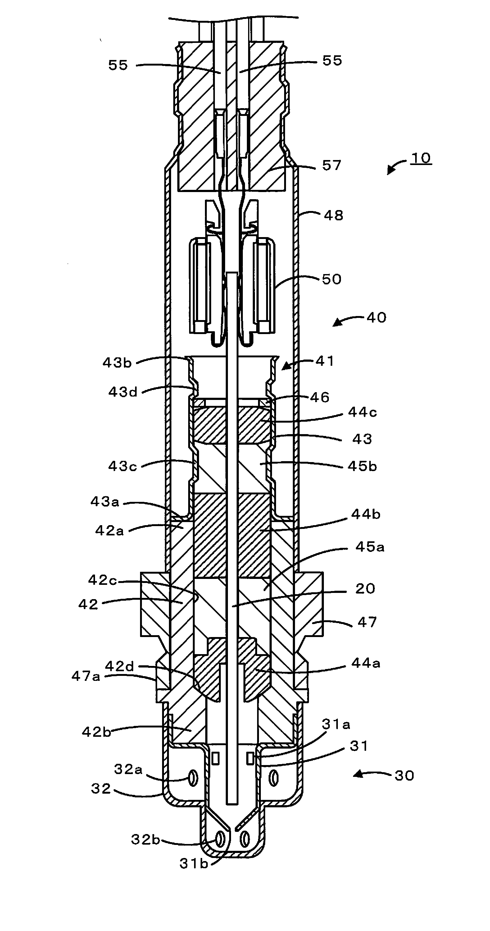
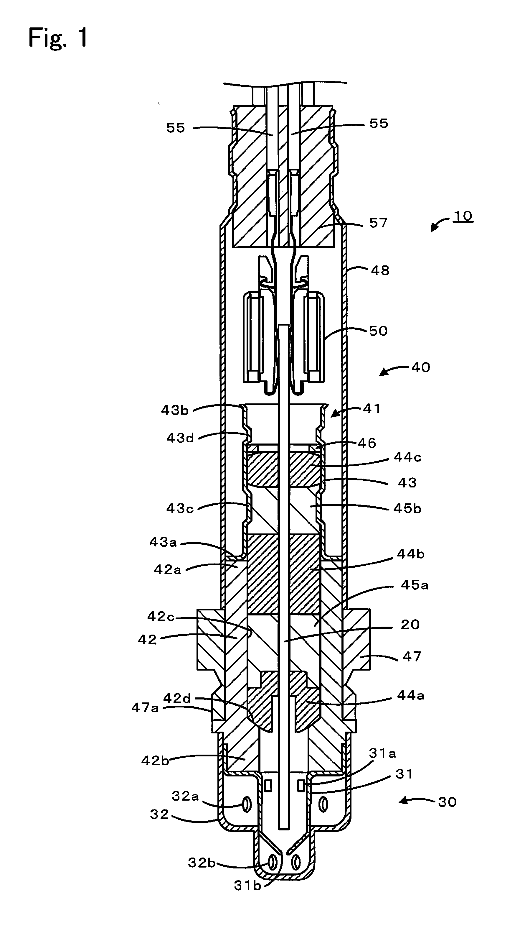
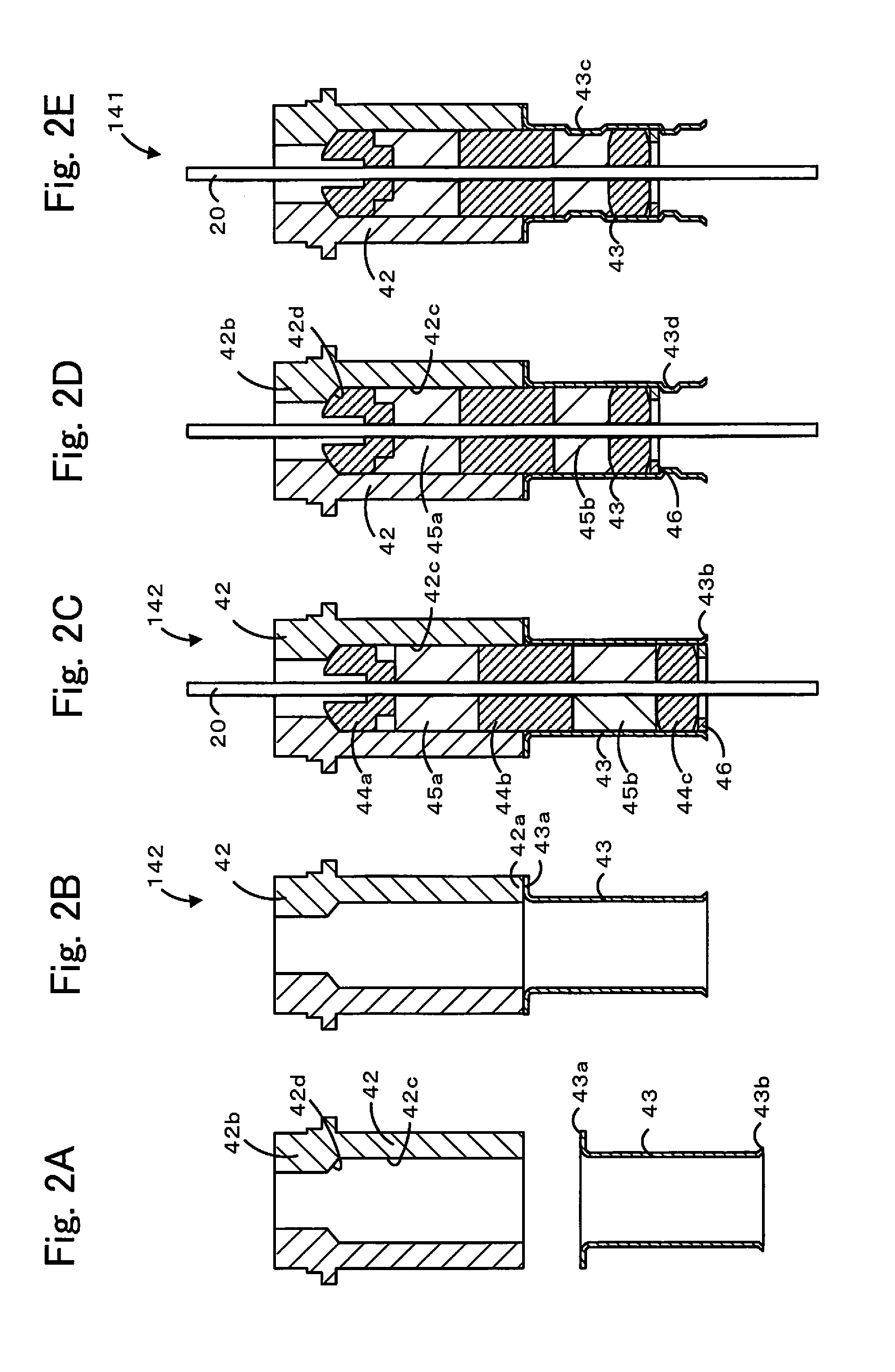
[0056]Experimental Examples 1 to 7 were each obtained, as a part of the gas sensor, by fabricating the primary assembly made up of the element enclosing member 341 and the sensor element 20 illustrated in FIG. 4, and by mounting the protective cover 30 and the nut 47, including the external threads 47a, to the primary assembly, thus fabricating the secondary assembly in the same manner as the above-described manufacturing method. Experimental Examples 1 to 7 had the same configuration except that the arithmetic average roughness Ra of the inner peripheral surface 42c was different among them. More specifically, the main hardware 42 and the inner tube 243 were made of stainless steel and formed by forging. The inner peripheral surface 42c of the main hardware 42 had the inner diameter of 9 mm and the axial length of 20.7 mm. The thicker wall portion 42b had the inner diameter of 5.9 mm and the axial length of 6.4 mm. The axial length of the inner tube 43 was 4.3 mm, and the inner dia...

experimental examples 8 to 28

[0057]Experimental Examples 8 to 14 were obtained by fabricating similar secondary assemblies to those in Experimental Examples 1 to 7 except that the sealing load applied to the powder compact 345a was changed to 1000 kgf. Experimental Examples 15 to 21 were obtained by fabricating similar secondary assemblies to those in Experimental Examples 1 to 7 except that the sealing load applied to the powder compact 345a was changed to 1400 kgf. Experimental Examples 22 to 28 were obtained by fabricating similar secondary assemblies to those in Experimental Examples 1 to 7 except that the sealing load applied to the powder compact 345a was changed to 2000 kgf. The amount of talc powder used in each of those Experimental Examples was 2.2 g.

[0058][Evaluation Tests]

[0059]The gas tightness effectuated by the powder compact 345a between each of the main hardware 42 and the inner tube 43 and the sensor element 20 was tested for the secondary assemblies of Experimental Examples 1 to 28. FIG. 6 is...


PUM

PropertyMeasurementUnit
arithmetic average roughnessaaaaaaaaaa
particle diameteraaaaaaaaaa

Abstract

In a gas sensor, a powder compact seals a void space between an inner peripheral surface of metal-made main hardware and a sensor element, and the inner peripheral surface has arithmetic average roughness of 0.5 to 5 μm. The gas sensor includes supporters, which are arranged in a penetration hole of the main hardware, which allow the sensor element to penetrate therethrough, and which press the powder compact in sandwiching relation from both sides in an axial direction. A surface of at least one of the supporters has the arithmetic average roughness of not more than 0.5 μm.

Description

CROSS-REFERENCE TO RELATED APPLICATIONS[0001]This application is a continuation application of U.S. patent application Ser. No. 14 / 643,516, filed on Mar. 10, 2015, which claims priority to Japanese Patent Application No. 2014-055867 filed in Japan on Mar. 19, 2014, the contents of each of which are hereby incorporated herein by reference.BACKGROUND OF THE INVENTION[0002]1. Field of the Invention[0003]The present invention relates to a gas sensor.[0004]2. Description of the Related Art[0005]Hitherto, there is known a gas sensor for detecting a concentration of specific gas, such as NOx, which is contained in target gas of measurement, e.g., exhaust gas from an automobile. For example, International Publication No. 2013 / 005491discloses a gas sensor including a sensor element that detects a concentration of specific gas, a tubular member through which the sensor element penetrates, and a cover disposed at a free end of the sensor element and having a gas inlet through which the specifi...

Claims


Application Information

Patent Timeline
Patent Type & Authority Applications(United States)
IPC IPC(8): G01N27/407
CPCG01N27/407G01N27/4078
Inventor ADACHI, YOSUKEMAKINO, MIYOSHIMASUDA, KOICHI
Owner NGK INSULATORS LTD
Why Eureka
Try Eureka