Wafer drying apparatus and wafer drying method

a drying apparatus and wafer technology, applied in drying machines, lighting and heating apparatus, drying machines, etc., can solve the problems of forming devices, reducing the performance of devices, and difficult to remove watermarks from wafers, so as to prevent the formation of watermarks on wafers that have been dried, and reduce the concentration of oxygen in liquid films.

Active Publication Date: 2016-12-22
EBARA CORP
View PDF35 Cites 6 Cited by
  • Summary
  • Abstract
  • Description
  • Claims
  • Application Information

AI Technical Summary

Benefits of technology

[0017]According to the above-described embodiments, liquid (e.g., pure water) on a wafer is sucked by the liquid suction nozzle, thereby forming a thinner liquid film. Therefore, an amount of oxygen dissolved in the liquid film is reduced, and as a result, the formation of the watermark can be prevented. Moreover, since the inert gas is supplied into the drying chamber, the oxygen is expelled from the drying chamber. Theref

Problems solved by technology

The watermark may cause a defect of devices formed on the wafer or a decrease in performance of the device

Method used


Image

  • Wafer drying apparatus and wafer drying method
  • Wafer drying apparatus and wafer drying method
  • Wafer drying apparatus and wafer drying method

Examples


Embodiment Construction

[0025]Embodiments will now be described with reference to the drawings.

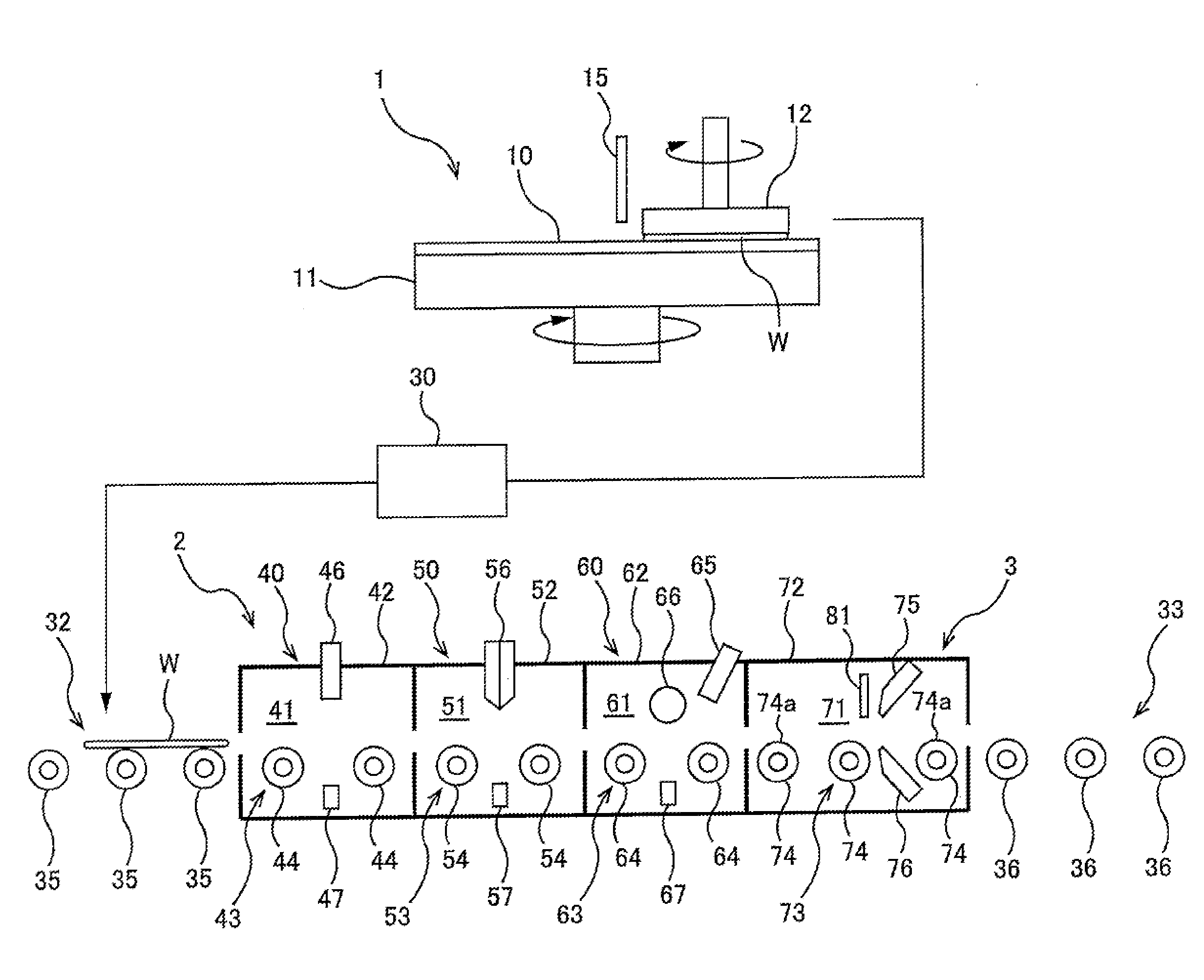
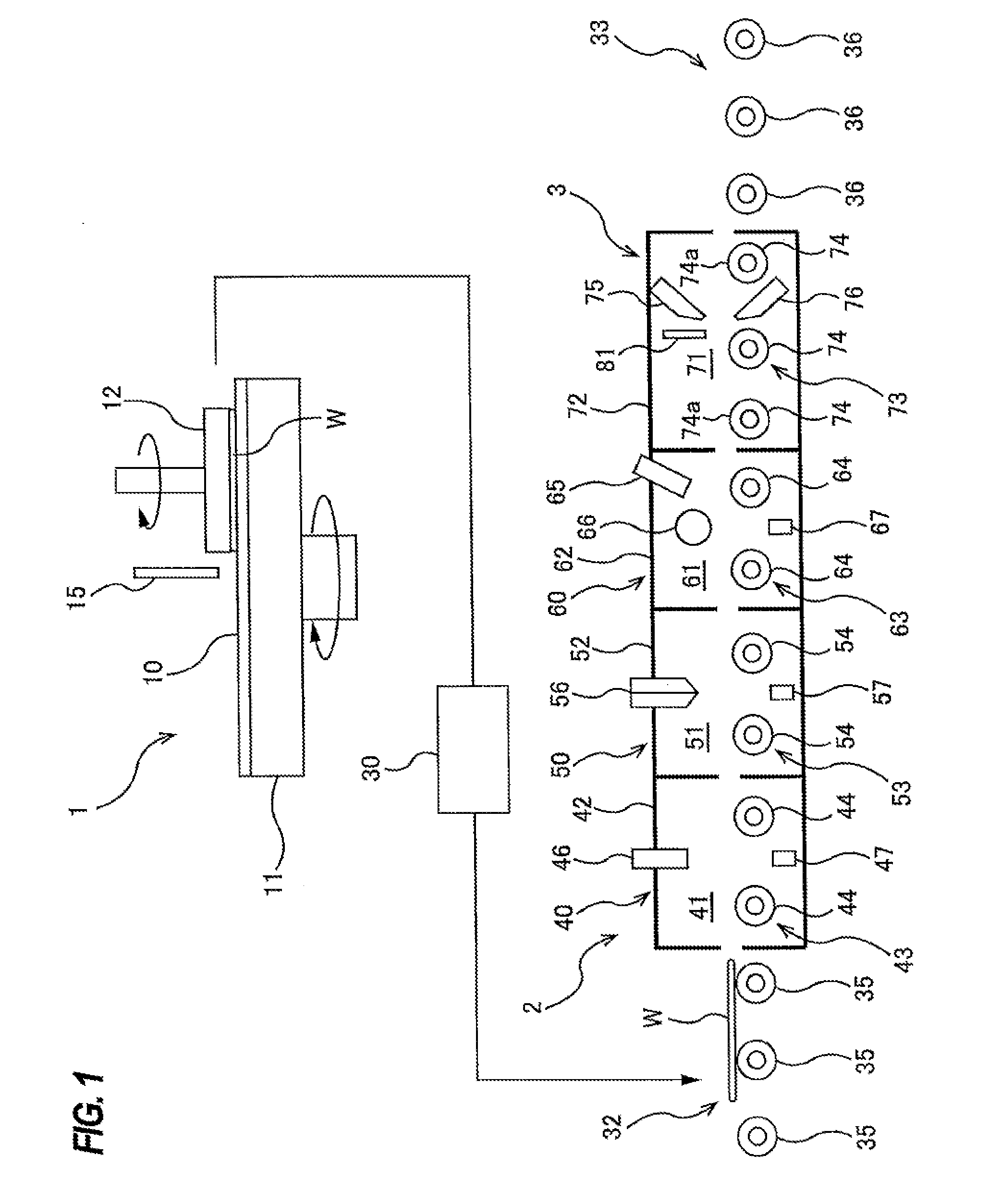
[0026]FIG. 1 is a schematic view of an entirety of a wafer processing apparatus which includes a wafer drying apparatus according to an embodiment. The wafer processing apparatus includes a polishing unit 1 for polishing a wafer W, a cleaning unit 2 for cleaning the polished wafer W, and a drying unit 3 for drying the cleaned wafer W. The drying unit 3 is an embodiment of the wafer drying apparatus.

[0027]The polishing unit 1 is a polishing apparatus for chemically mechanically polishing a wafer W. The polishing unit 1 includes a polishing table 11 for supporting a polishing pad 10, a polishing head 12 for holding and rotating the wafer W, and a polishing-liquid supply nozzle 15 for supplying a polishing liquid (or slurry) onto the polishing pad 10. An upper surface of the polishing pad 10 provides a polishing surface for polishing a surface of the wafer W. The polishing table 11 is coupled to a table motor (not s...


PUM


Abstract

A wafer drying apparatus capable of preventing formation of a watermark is disclosed. The wafer drying apparatus includes: a conveying mechanism configured to convey a wafer in a drying chamber; an inert-gas jet nozzle disposed above the conveying mechanism and configured to form a descending jet of an inert gas; and a liquid suction nozzle disposed upstream of the inert-gas jet nozzle with respect to a conveying direction of the wafer. A distance between the liquid suction nozzle and a surface of the wafer when the wafer is being conveyed by the conveying mechanism is in a range of 1 mm to 2 mm.

Description

CROSS REFERENCE TO RELATED APPLICATION[0001]This document claims priority to Japanese Patent Application Number 2015-124538 filed Jun. 22, 2015, the entire contents of which are hereby incorporated by reference.BACKGROUND[0002]A CMP process of chemically mechanically polishing a wafer is performed by rubbing a surface of the wafer against a polishing surface while supplying a polishing liquid (i.e., slurry), containing abrasive grains, onto the polishing surface. The abrasive grains and polishing debris remain on the polished wafer. Thus, the wafer is sent to a cleaning chamber and cleaned in the cleaning chamber. Cleaning of the wafer is performed by supplying of a chemical liquid, rinsing of a wafer with pure water, and the like. The cleaned wafer is further transported to a drying chamber, where the wafer is dried.[0003]The polished wafer may have an exposed silicon on its surface. If the wafer is dried with pure water present on the silicon, a watermark is likely to be formed on...

Claims


Application Information

Patent Timeline
IPC IPC(8): H01L21/67F26B5/12F26B21/14H01L21/677
CPCH01L21/67034F26B21/14F26B5/12H01L21/67739H01L21/67028H01L21/6776F26B15/12F26B21/004H01L21/02046H01L21/02307H01L21/67017H01L21/67126H01L21/6715H01L21/67715F26B5/16F26B2200/12
Inventor IMAI, MASAYOSHIHAMADA, SATOMI
Owner EBARA CORP
Why Eureka
Try Eureka