Contactless battery system utilizing a bidirectional power converter

a power converter and contactless technology, applied in the field of power converters, can solve the problems of adding layers of complexity, affecting the reliability of the battery system, and affecting the reliability of the battery system, and thus being unavoidabl

Active Publication Date: 2016-12-22
ENOVATE MEDICAL
View PDF3 Cites 15 Cited by
  • Summary
  • Abstract
  • Description
  • Claims
  • Application Information

AI Technical Summary

Benefits of technology

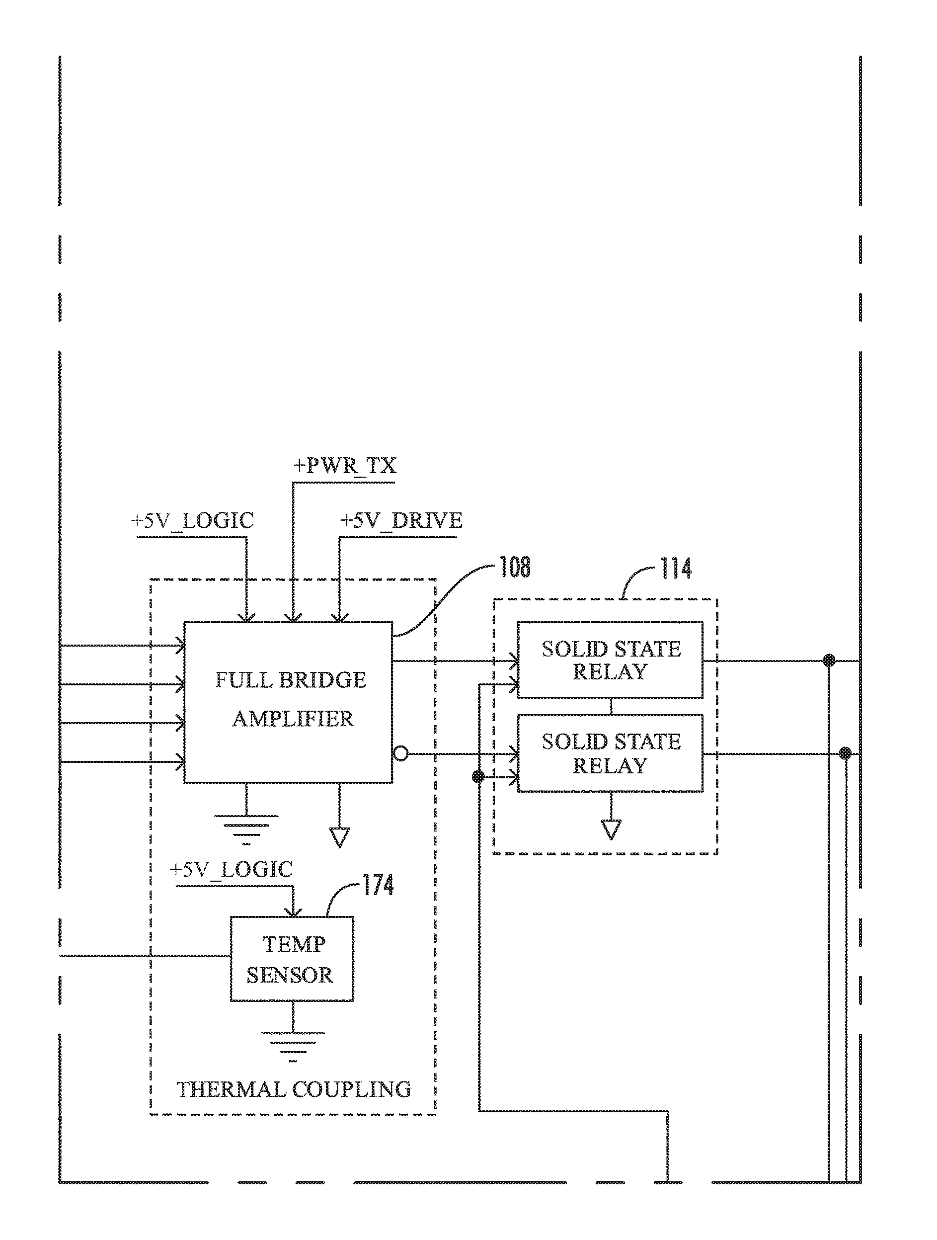
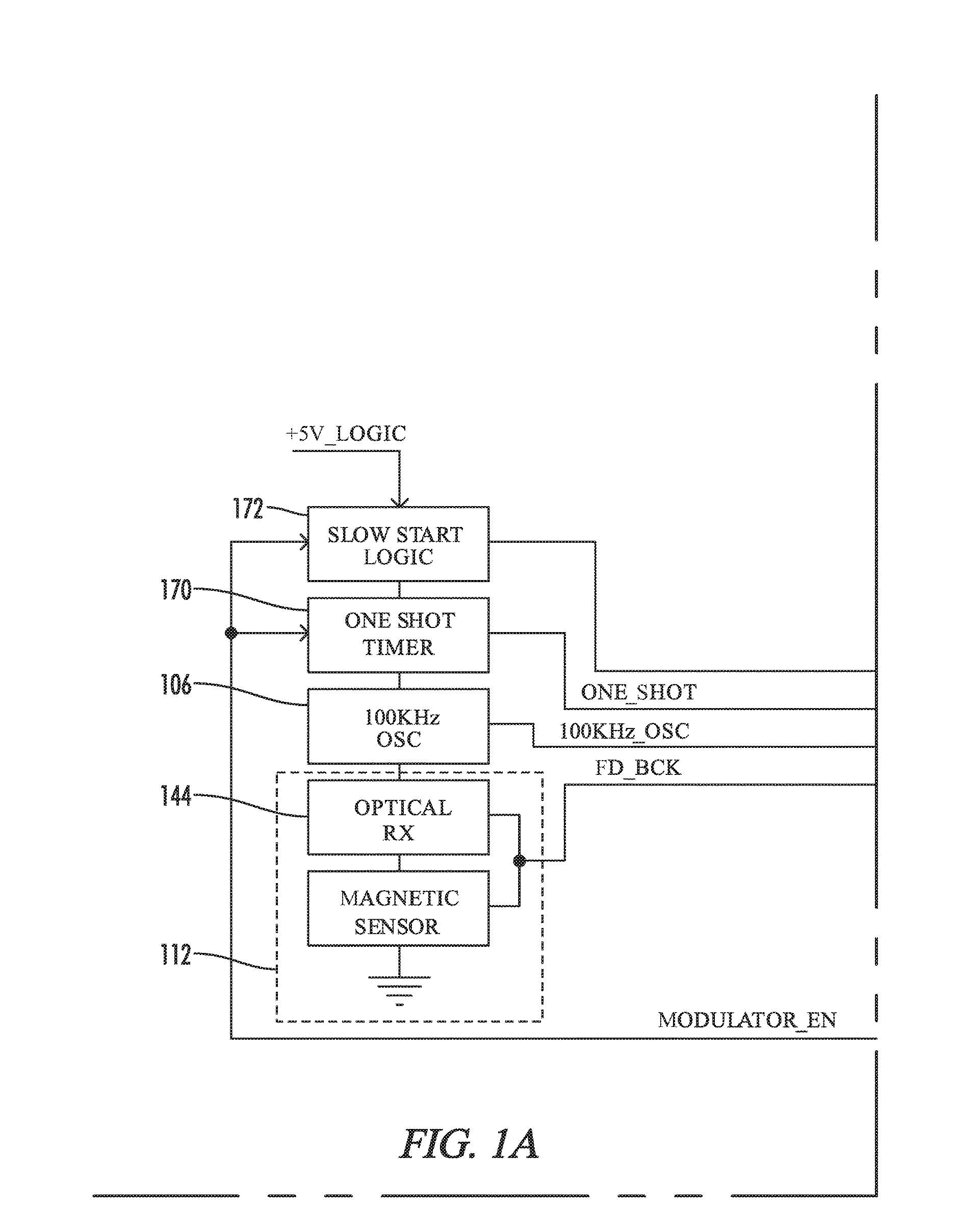
[0008]Aspects of the present invention provide a bidirectional power converter circuit. The bidirectional power converter circuit is capable of both transmitting and receiving power, such that the bidirectional power converter circuit of the present invention may be used as the main component in multiple wireless power converter designs. The bidirectional power converter circuit is controlled via a hysteresis loop such that the bidirectional power converter circuit can compensate in near real time for variations and even changes in transmitter and receiver coil locations without damaging any components of the system. In one aspect, a contactless battery unit incorporates a bidirectional power converter to provide a battery in a fully sealed housing with no external contacts to either a charger or a device to be powered by the battery.

Problems solved by technology

Designing circuits and laying out printed circuit boards is a time consuming and expensive process.
Further, having multiple circuits and boards requires tracking multiple revisions of multiple circuits and printed circuit boards, which adds layers of complexity.
Having multiple circuits and board layouts, each with multiple revisions is therefore heretofore unavoidable.
Wireless charging systems are limited by, inter alia, size, space, and transmitter / receiver orientation limitations.
Further, wireless charging systems are currently limited by distance and / or orientation.
If the pitch or X-Y translation is not accurate, the transmitter may be damaged, requiring replacement of the transmitter circuit board.
Thus, wireless charging systems that cannot compensate for variations in transmitter and receiver coil relative locations are difficult to manage and repair, and they are not practical for many uses in the field.

Method used


Image

  • Contactless battery system utilizing a bidirectional power converter
  • Contactless battery system utilizing a bidirectional power converter
  • Contactless battery system utilizing a bidirectional power converter

Examples


Embodiment Construction

[0018]While the making and using of various embodiments of the present invention are discussed in detail below, it should be appreciated that the present invention provides many applicable inventive concepts that can be embodied in a wide variety of specific contexts. The specific embodiments discussed herein are merely illustrative of specific ways to make and use the invention and do not delimit the scope of the invention.

[0019]To facilitate the understanding of the embodiments described herein, a number of terms are defined below. The terms defined herein have meanings as commonly understood by a person of ordinary skill in the areas relevant to the present invention. Terms such as “a,”“an,” and “the” are not intended to refer to only a singular entity, but rather include the general class of which a specific example may be used for illustration. The terminology herein is used to describe specific embodiments of the invention, but their usage does not delimit the invention, excep...


PUM


Abstract

A bidirectional power converter circuit is controlled via a hysteresis loop such that the bidirectional power converter circuit can compensate for variations and even changes in transmit and receive coil locations without damaging components of the system. Because the bidirectional power converter is capable of both transmitting and receiving power (at different times), one circuit and board may be used as the main component in multiple wireless power converter designs. A first bidirectional power converter is employed in a sealed battery unit having no external electrical contacts. A second bidirectional power converter is employed in a corresponding cart bidirectional power converter assembly. The battery unit and the cart bidirectional power converter assembly cooperate to wirelessly transmit power from the battery unit to a load of the cart bidirectional power converter assembly and from a power source to the battery unit via the cart bidirectional power converter assembly.

Description

CROSS-REFERENCES TO RELATED APPLICATIONS[0001]This application claims priority to, and hereby incorporates by reference in its entirety, U.S. Provisional Patent Application Ser. No. 62 / 146,091 entitled “WIRELESS POWER SYSTEM” filed on Apr. 10, 2015.[0002]A portion of the disclosure of this patent document contains material that is subject to copyright protection. The copyright owner has no objection to the reproduction of the patent document or the patent disclosure, as it appears in the U.S. Patent and Trademark Office patent file or records, but otherwise reserves all copyright rights whatsoever.STATEMENT REGARDING FEDERALLY SPONSORED RESEARCH OR DEVELOPMENT[0003]Not ApplicableREFERENCE TO SEQUENCE LISTING OR COMPUTER PROGRAM LISTING APPENDIX[0004]Not ApplicableBACKGROUND OF THE INVENTION[0005]The present invention relates generally to power converters. More particularly, this invention pertains to bidirectional power converters and sealed batteries.[0006]Designing circuits and la...

Claims


Application Information

Patent Timeline
Patent Type & Authority Applications(United States)
IPC IPC(8): H02J7/02H02M1/08H02J7/04H02J50/80H02J50/10
CPCH02J7/025H02J50/80H02M1/08H02J7/04H02J50/10H02M7/5383H02M7/797H02J50/90H02J7/007192H02M7/70H02J7/00714H02J50/20H02J50/12H04B1/16H04B1/40
Inventor BLAKELY, GEORGEWAID, GORDON
Owner ENOVATE MEDICAL
Why Eureka
Try Eureka