

Light source device and projector
a light source device and projector technology, applied in the direction of picture reproducers using projection devices, instruments, lenses, etc., can solve the problem that the combination of dielectric multi-layer films cannot be performed in good condition, and achieve the effect of preventing the influence of photo-elastic
- Summary
- Abstract
- Description
- Claims
- Application Information
AI Technical Summary
Benefits of technology
Problems solved by technology
Method used
Image

Examples
first embodiment
[0033]The projector according to the present embodiment is an example of a projector using three transmissive liquid crystal light valves.
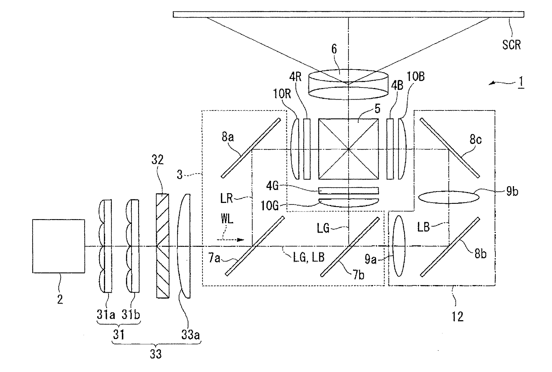
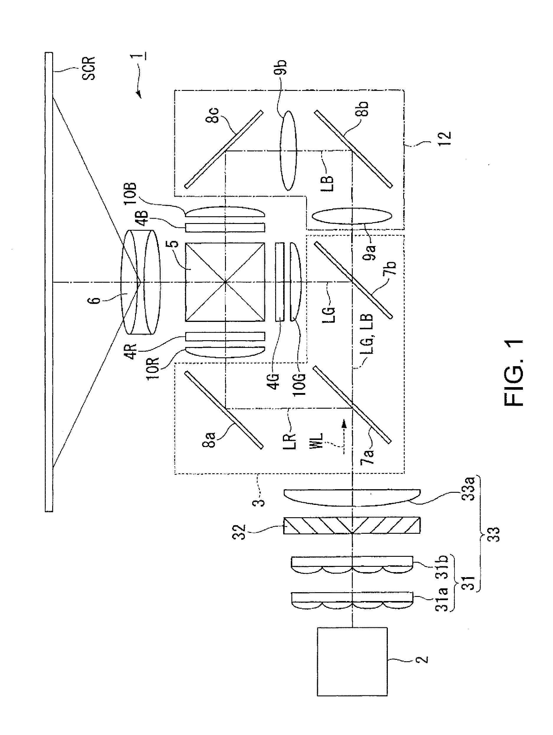
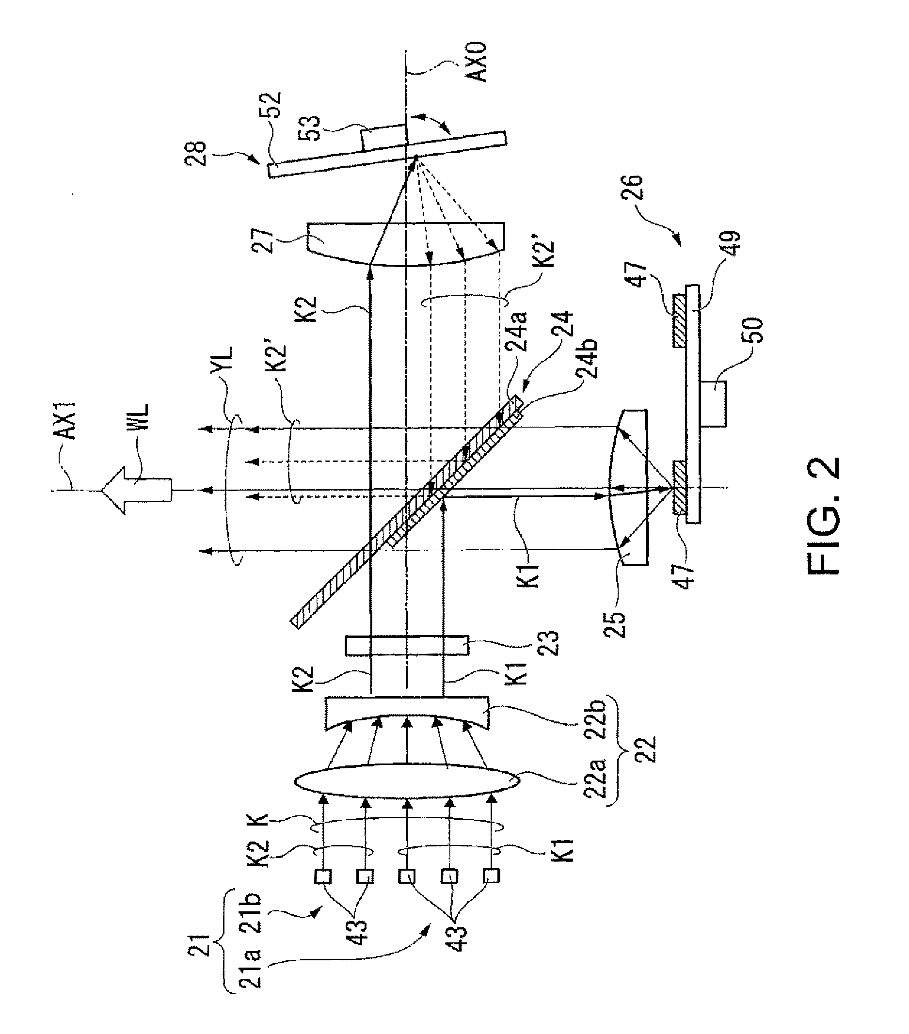
[0034]FIG. 1 is a schematic configuration diagram showing a projector according to the present embodiment. FIG. 2 is a schematic configuration diagram showing a light source device according to the present embodiment.
[0035]As shown in FIG. 1, the projector 1 according to the present embodiment is a projection-type image display device for displaying a color image on a screen SCR. The projector 1 is generally provided with the light source device 2, a color separation optical system 3, a relay optical system 12, an integrator optical system 31, a polarization conversion element 32, an overlapping lens 33a, a light modulation device 4R for red light, a light modulation device 4G for green light, a light modulation device 4B for blue light, a color combining optical system 5, and a projection optical system 6. The light modulation device 4R for the r...
second embodiment
[0106]Subsequently, a light source device according to a second embodiment of the invention will be described. The difference between the present embodiment and the first embodiment is the configuration of the relay optical system, and the rest of the configuration is common. Therefore, in the following description, regarding the constituents and the members common to the first embodiment and the present embodiment, the common reference symbols are used, and the detailed description will be omitted.
[0107]FIG. 5 is a diagram showing the relay optical system of the light source device according to the present embodiment. As shown in FIG. 5, the relay optical system 12A of the present embodiment has a third lens array 70, a fourth lens array 71, a first reflecting mirror 72, a second reflecting mirror 73, and an overlapping lens 74.
[0108]It should be noted that in the present embodiment, the first reflecting mirror 72 corresponds to a “third reflecting element” of the appended claims, ...
third embodiment
[0115]Subsequently, a light source device according to a third embodiment of the invention will be described. The difference between the present embodiment and the embodiments described above is the configuration of the light source device, and the rest of the configuration is common. Therefore, in the following description, regarding the constituents and the members common to the embodiments described above and the present embodiment, the common reference symbols are used, and the detailed description will be omitted.
[0116]FIG. 6 is a diagram showing a configuration of a light source device 2A according to the present embodiment.
[0117]As shown in FIG. 6, the light source device 2A according to the present embodiment is provided with the light source unit 21, the afocal optical system 22, the uniform illumination optical system 23, a light separating / combining element 124, the first pickup lens 25, the phosphor wheel 26 having a phosphor layer, the second pickup lens 27, and the rot...
PUM
 Abstract
Description
Claims
Application Information