System And Method For Regulated And/Or Limited Speed Control
a technology of limited speed and control system, applied in the direction of braking system, vehicle position/course/altitude control, instruments, etc., can solve the problem that users are not able to apply the full braking force, and achieve the effect of improving fitness and/or strength
- Summary
- Abstract
- Description
- Claims
- Application Information
AI Technical Summary
Benefits of technology
Problems solved by technology
Method used
Image
Examples
first example
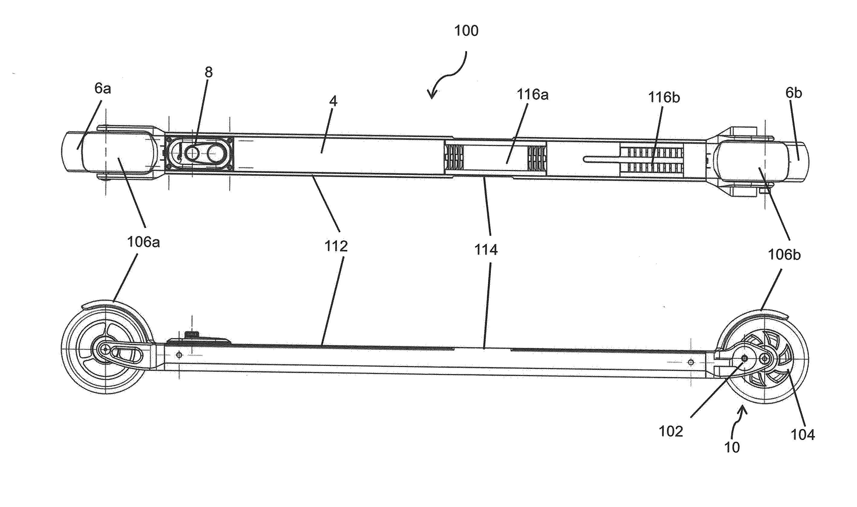
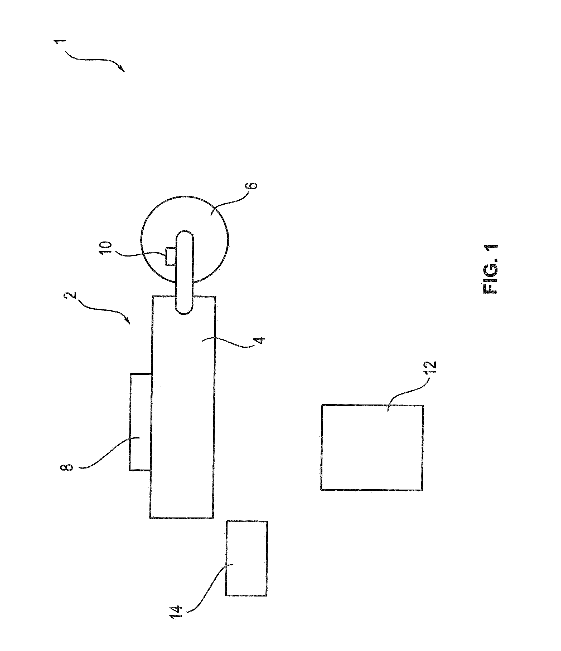
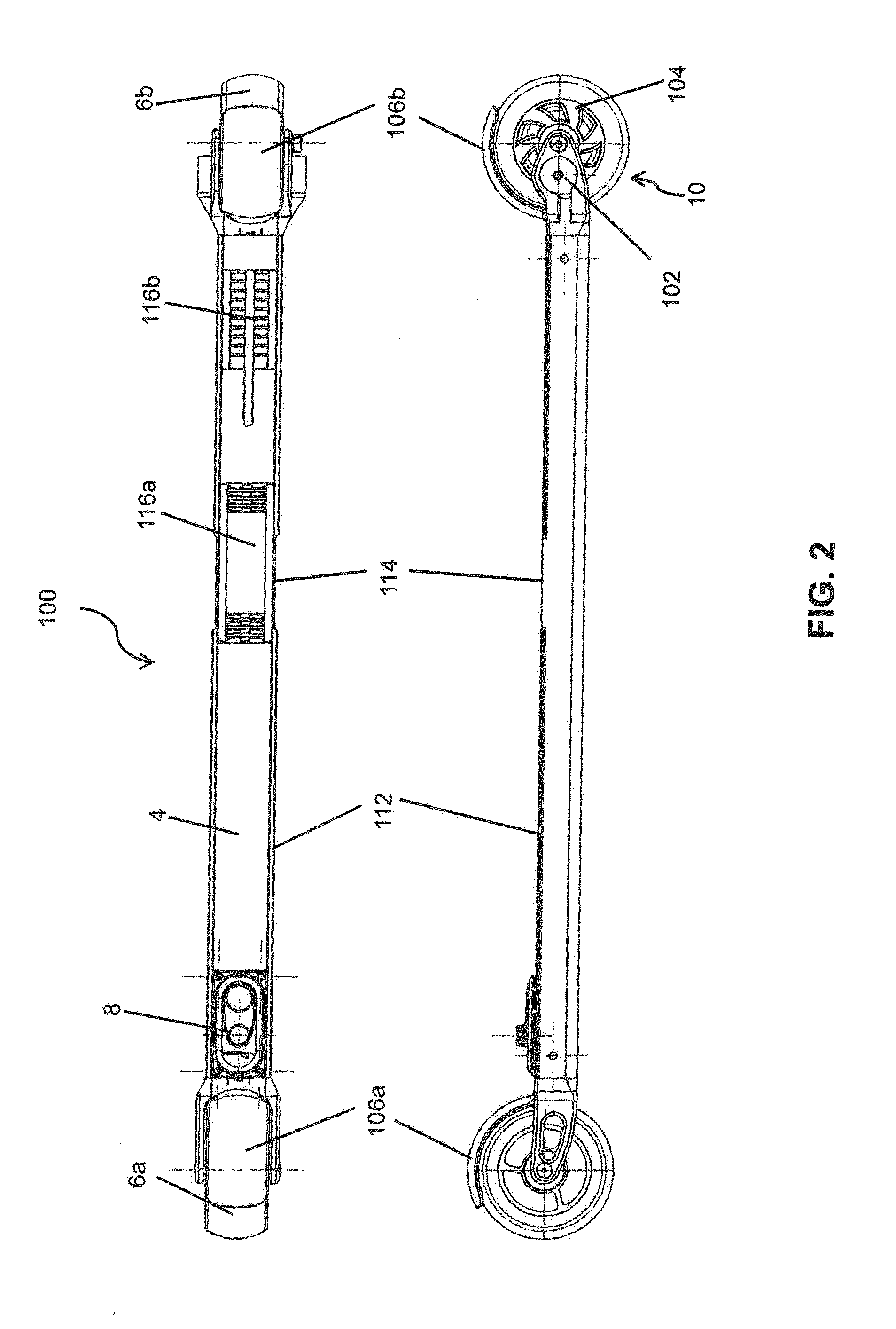
[0092]With reference to FIG. 12, the first example of operation is explained. As stated above, the actuation means 134 is actuated by a user when a braking force is to be applied to the one or more wheels 6. Whether the actuation means 134 is a pivoted trigger, sliding trigger, push button, or otherwise, the actuation means 134 is provided with a certain range of travel. That is, the actuation means 134 is adapted to move from a start or initial position that imparts no braking force to the one or more wheels 6, to a final position that imparts a maximal braking force.
[0093]In the first example, the range of travel of the actuation means 134 is 100 percent. That is, the designed range of the actuation means 134 is accessible by the user when operating the actuation means 134.
[0094]The restriction means 14 may be provided in the user actuator 12, but may equally be located in the control unit 8. In either situation, the actuation means 134 provides an indication of the braking force ...
second example
[0104]The second example is similar to the first example, but differs in that a mechanical limit on the actuation of the actuation means 14 is provided. Referring to FIG. 13, the restriction means 14 may comprise a mechanical stopper 136, such as a pin or screw. The mechanical stopper 136 is provided to physically limit the travel of the actuation means 134. For example, the mechanical stopper 136 may be adjusted to limit the movement of the actuator means 134 to only 50% of its capability.
[0105]The mechanical stopper 136 may be adjustable so as to increase or decrease the available travel of the actuation means 134 to the user. This could be via a mechanical adjustment, such as the user physically adjusting the mechanical stopper 136; in the case of a screw, for example, the user tightens or loosens the screw via a screw driver or the like. Alternatively, the adjustment may be performed via the use of driving means 138 that is adapted to drive the mechanical stopper 136 closer to o...
third example
[0111]The third example includes providing a non-linear mapping of the actuation of the actuation means 134.
[0112]In this example, the user actuator 12 may be provided with a full range of actuation. However, the actuation of the actuation means 134 is provided such that the actuation of the actuation means 134 is staggered. FIG. 15 shows a graph of force against travel distance. In operation of the actuation means 134, the user may be provided with a feedback force. In a wired connection between the actuator means 134 and the one or more brake units 10, this is the contact force of the brake piston 102 or brake pads 127 actuating against the disc brake 104 or the wheel 6.
[0113]In the linear case, the feedback force is directly proportional to the travel distance or actuation distance of the actuation means 134, as indicated by the line L. In the third example, the feedback force is applied non-linearly, as exemplified by the line N. According to line N, when the actuator means 134 ...
PUM
 Abstract
Description
Claims
Application Information
 - R&D
- Intellectual Property
- Life Sciences
- Materials
- Tech Scout
- Unparalleled Data Quality
- Higher Quality Content
- 60% Fewer Hallucinations
Browse by: Latest US Patents, China's latest patents, Technical Efficacy Thesaurus, Application Domain, Technology Topic, Popular Technical Reports.
© 2025 PatSnap. All rights reserved.Legal|Privacy policy|Modern Slavery Act Transparency Statement|Sitemap|About US| Contact US: help@patsnap.com


