Detection device

a detection device and detection method technology, applied in the field of detection devices, can solve the problems of affecting the use of users, requiring operators and a lot of time to precisely detect additives in the lab, and all the methods need high-tech and expensive equipment for detection, so as to simplify the preparation process, facilitate and fast operation, and simplify the effect of operation property

Inactive Publication Date: 2016-12-29
NATIONAL TSING HUA UNIVERSITY
View PDF2 Cites 3 Cited by
  • Summary
  • Abstract
  • Description
  • Claims
  • Application Information

AI Technical Summary

Benefits of technology

[0010]In view of the foregoing, an objective of the present invention is to provide a detection device, which has the simple operation property as the existing testing strips and is advantageous in simplified preparing process before testing and an easy and fast operation, thereby improving the sampling and detecting speeds and the application safety.

Problems solved by technology

This is because the food products may contain some remained bad substances, which exist in the raw materials or are generated during the manufacturing processes.
However, these detection methods all need a high-tech and expensive equipment for detection, and require operators and a lot of time to precisely detect the additives in the labs.
However, the user has to carry the testing strip all the time, which may bother the users indeed.
In addition, the existing testing strips are almost made by many processes, and the added substances in the testing strips will cause the risk of the safety of the testing strips.
Moreover, in order to obtain a precise testing result, the pipette must be well cleaned before the testing procedure, which makes the detection procedure more complex.

Method used


Image

  • Detection device
  • Detection device
  • Detection device

Examples


experimental example 1

The Layout of the Reaction Areas and the Color Intensity Test

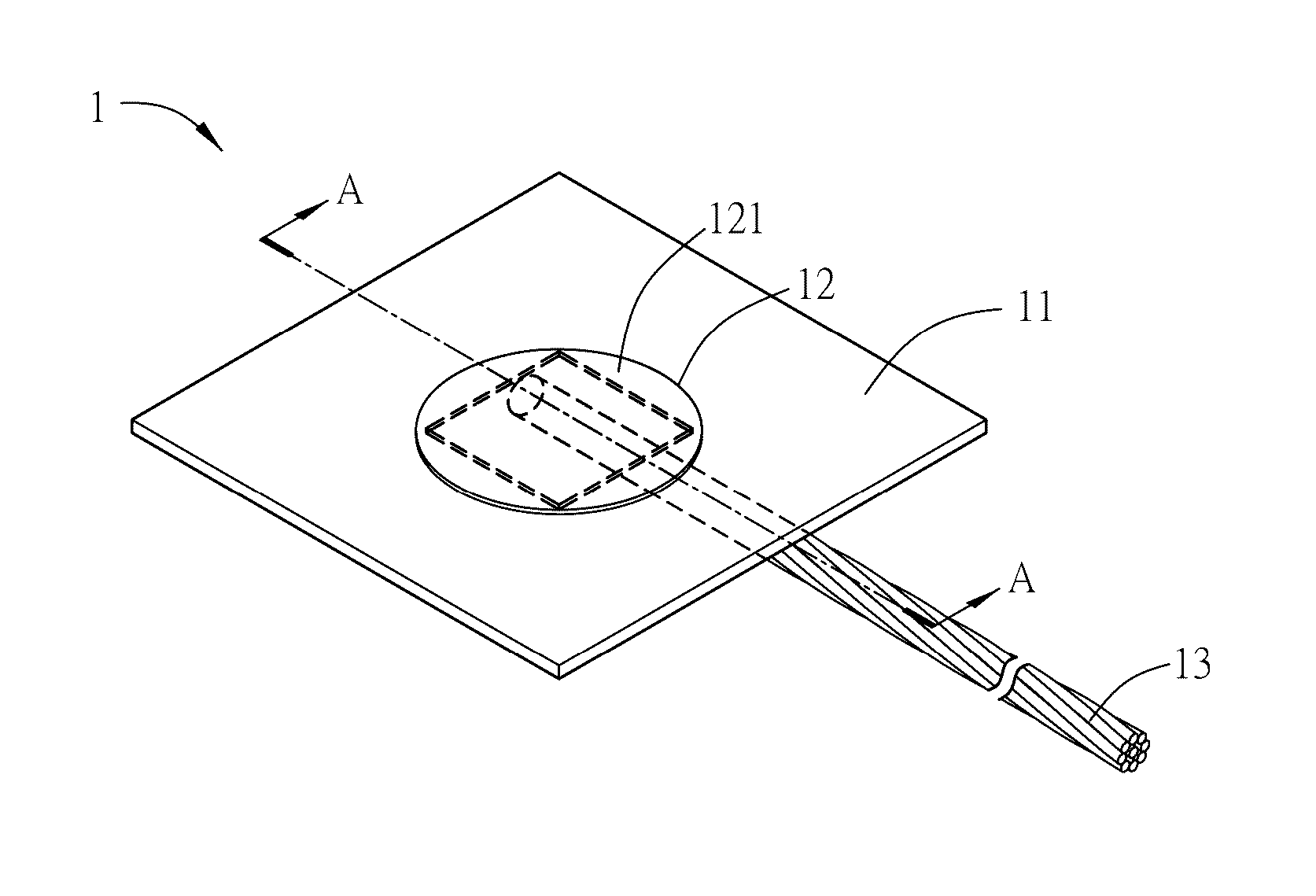
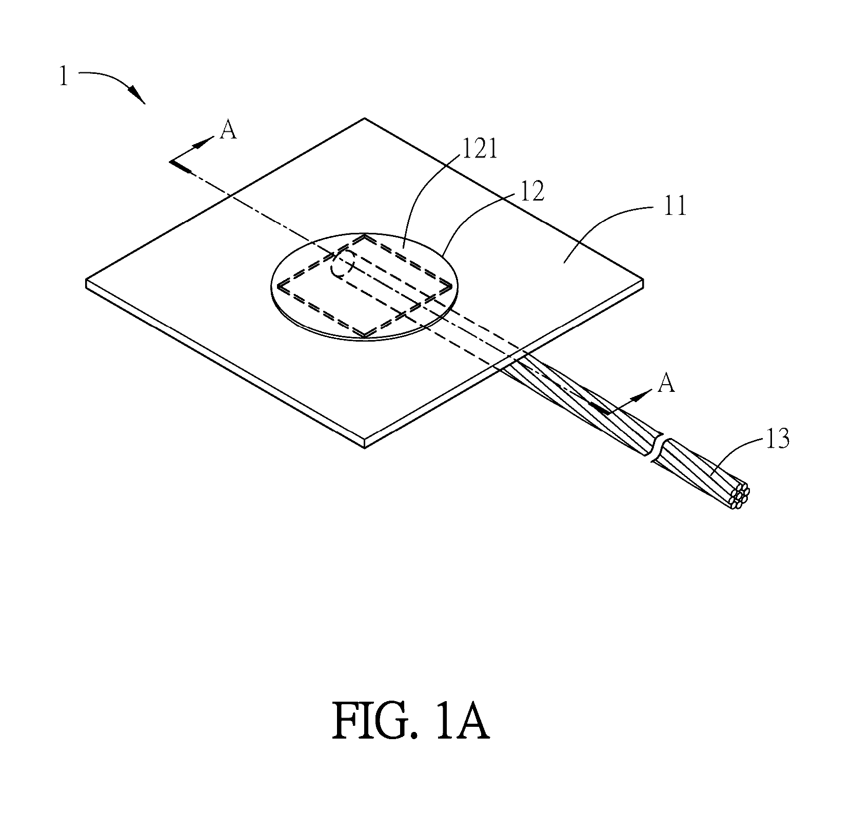
[0083]FIG. 11 is a schematic graph showing the mean intensities with respect to different reaction area layouts in the detection device 1i. Referring to FIG. 11, the example is to check whether the reaction unit 12i is configured with the hydrophobic non-reaction area 122i. A blue aqueous solution is transported through the wire transporting unit 13i to the detection device 1i (test A) and to a detection device without non-reaction area (test B). The color results of tests A and B are collected by naked eyes, camera or scanner. The experimental results indicate that the color intensities between the test A (using the detection device 1i with hydrophobic non-reaction area 122i) and the test B (using the detection device without hydrophobic non-reaction area) are obviously different.

experimental example 2

The Test for the Relationship Between the Length of the Wire Transporting Unit and the Absorption Volume

[0084]At first, a fine balance (sensitivity=1 mg) is used to measure the weight of a wire transporting unit 112i before absorbing water. Next, the wire transporting unit 112i is hanged on the edge of a beaker, and only the tail part (1-2 cm) of the wire transporting unit 112i is contact with solution. The solution in the beaker is absorbed by the wire transporting unit 112i based on capillary phenomenon until the entire wire transporting unit 112i (the other end hanged on the beaker) is also full filled with the solution. Then, the wire transporting unit 112i is weighted again. Afterwards, the wire transporting unit 112i is put on the reaction unit 12i (as the configuration of detection device 10. Accordingly, the reaction area 121i of the reaction unit 12i, which has better absorption ability, can absorb the solution from the wire transporting unit 112i. Then, the wire transporti...

experimental example 3

Detecting Nitrite by the Detection Device 1j

[0086]To be noted, the structure of the applied detection device 1j is mostly the same as that of the detection device 1i of the previous embodiment. The difference therebetween is that the detection device 1j includes three reaction areas 121j.

[0087]The detection reagent is dropped by micropipette (Gilson, Inc.) onto the reaction areas 121j of the detection device 1j. The detection reagent includes 50 mmol / L sulfanilamide (≧99%, Sigma-Aldrich), 330 mmol / L citric acid (≧99.5%, Sigma-Aldrich) and 10 mmol / L N-(1-naphthyl)ethylene diamine (≧98%, Sigma-Aldrich). After adding the detection reagent, the detection device 1j is dried for 15 minutes at 25° C. Then, the wire transporting unit 13j of the detection device 1j is used to contact and collect the test samples. The test samples include a food sample containing nitrite standard diluted in hot pot soup (test A) and a buffer sample containing nitrite standard diluted in distilled deionized ...


PUM

PropertyMeasurementUnit
included angleaaaaaaaaaa
densityaaaaaaaaaa

Abstract

A detection device includes a carrying unit, at least a reaction unit, a wire transporting unit, and a guiding unit. The carrying unit includes at least a hole, and the reaction unit is disposed on one side of the hole. The reaction unit includes at least a reaction area, which includes a hydrophilic material containing a detection reagent. The wire transporting unit is disposed on the other side of the hole and includes a sampling end and a transporting end. The guiding unit is in contact with the reaction unit and the transporting end. The guiding unit collects a test sample through the transporting end and provides at least a part of the test sample to react with the detection reagent. The detection device adopts the wire transporting unit to replace the pipette for collecting the test sample without directly contacting the detection area with the sample source.

Description

CROSS REFERENCE TO RELATED APPLICATIONS[0001]This Non-provisional application claims priority under 35 U.S.C. §119(a) on Patent Application No(s). 104120708 filed in Taiwan, Republic of China on Jun. 26, 2015, the entire contents of which are hereby incorporated by reference.BACKGROUND OF THE INVENTION[0002]Field of Invention[0003]The present invention relates to a detection device and, in particular, to a detection device, which can transport the test sample to the reaction unit through a wire transporting unit based on capillary phenomenon.[0004]Related Art[0005]As the rising of health consciousness, the concept of self-detection in house is more and more popular. The self-detection allows the users to easily and simply detect the simple physiological status or the food safety anytime and anywhere. The detection of physiological status can help the general users to check the health statuses of themselves and, in particular, assist the patients to enhance the therapeutic effects an...

Claims


Application Information

Patent Timeline
Patent Type & Authority Applications(United States)
IPC IPC(8): B01L3/00G01N33/02
CPCB01L3/5023G01N33/02B01L2300/0825B01L2300/069B01L2300/089B01L2300/12B01L2300/165B01L2200/02G01N35/00B01L2200/027B01L2300/0809B01L2300/0864B01L2300/087
Inventor CHENG, CHAO-MINTSAI, MEI-JOU
Owner NATIONAL TSING HUA UNIVERSITY
Why Eureka
Try Eureka