Dual Purpose Heat Transfer Surface Device

a heat transfer surface and dual-purpose technology, applied in indirect heat exchangers, machines/engines, lighting and heating apparatus, etc., can solve the problem that the velocity profile is usually not sufficient to meet the desired velocity profile at the duct burner, and achieve the effect of improving the velocity profile, prolonging the surface characteristics, and improving the velocity profil

Inactive Publication Date: 2016-12-29
HRST
View PDF15 Cites 5 Cited by
  • Summary
  • Abstract
  • Description
  • Claims
  • Application Information

AI Technical Summary

Benefits of technology

[0015]In some embodiments, a heat transfer panel, or multiple panels vary the exhaust gas flow characteristics from a gas or combustion turbine across a transverse and longitudinal plane, thereby eliminating the need for a separate flow distribution device. The heat transfer panel, or multiple panels may have varied extended surface characteristics disposed along the length of the heat transfer tubes. Alternatively, the heat transfer tube to heat transfer tube separation or relative spacing distance in either the transverse or longitudinal direction may be modified to achieve the differential flow characteristics required to redistribute the exhaust gas flow across a transverse plane. One alternative in addition to heat transfer of this panel, may be to create uniform gas flow and a desired velocity profile for the exhaust gas.
[0016]In some embodiments there may be a small number of rows of heat absorbing heat transfer tubes upstream of the duct burner or other critical component. The pressure drop across the rows of heat absorbing tubes improves the velocity profile of the exhaust gas flow, but the velocity profile is usually not sufficient to satisfy the desired velocity profile at the duct burner or other critical component. Note that a large tube bank upstream of the duct burner or other critical component would sufficiently improve the velocity profile, but thermal design constraints typically dictate the use of a small tube bank upstream of the duct burner or other critical component.

Problems solved by technology

The pressure drop across the rows of heat absorbing tubes improves the velocity profile of the exhaust gas flow, but the velocity profile is usually not sufficient to satisfy the desired velocity profile at the duct burner or other critical component.
Note that a large tube bank upstream of the duct burner or other critical component would sufficiently improve the velocity profile, but thermal design constraints typically dictate the use of a small tube bank upstream of the duct burner or other critical component.

Method used


Image

  • Dual Purpose Heat Transfer Surface Device
  • Dual Purpose Heat Transfer Surface Device
  • Dual Purpose Heat Transfer Surface Device

Examples


Embodiment Construction

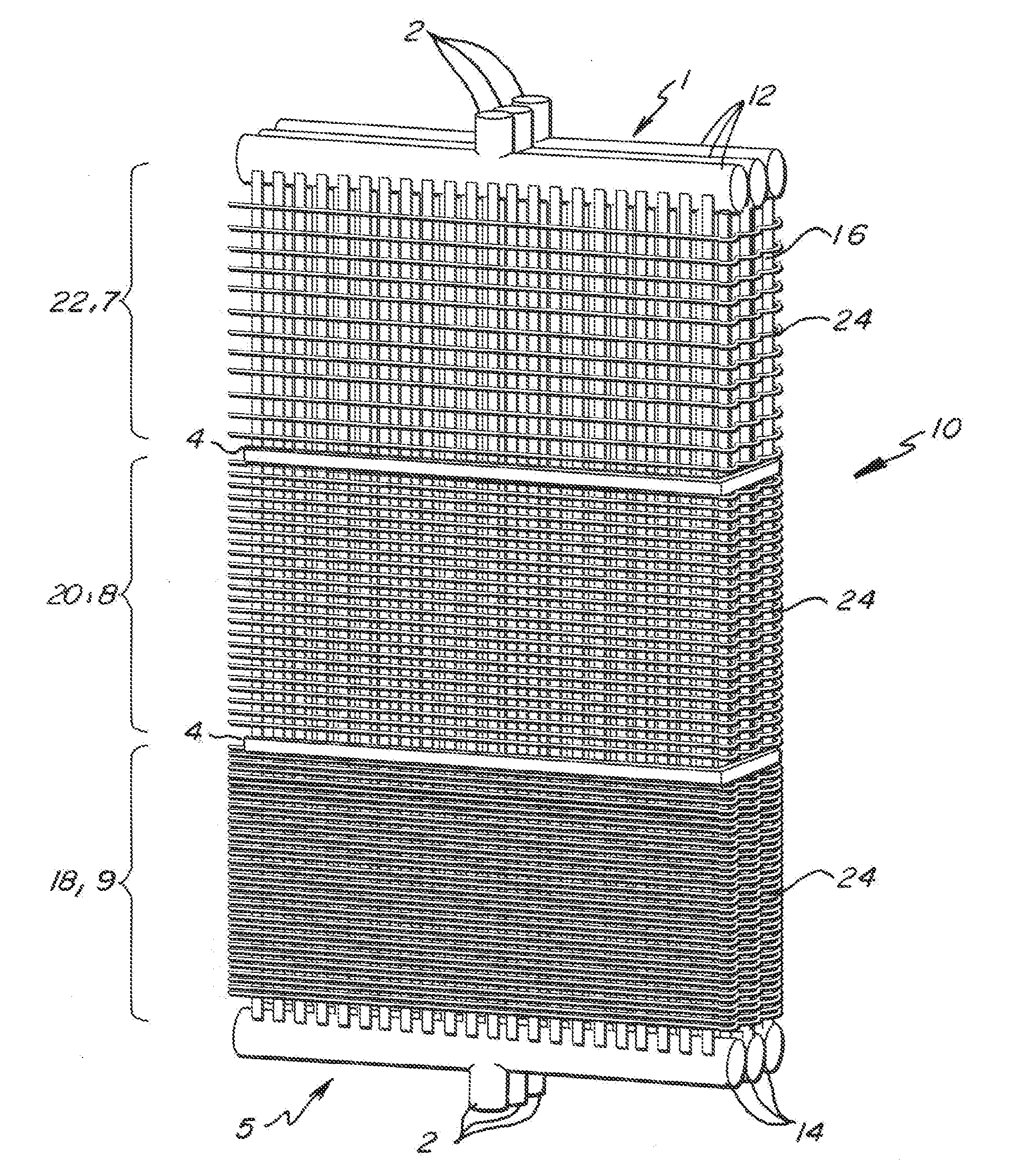
[0057]In at least one embodiment of the present invention as depicted in FIGS. 9, 10, 11, 12, 13, and 18 a tube panel 10 is shown. Tube panel 10 may be formed of an upper header 1 and lower header 5 with interconnecting inlet piping 12 and outlet piping 14 having header nozzles 2. In at least one embodiment, the tube panel 10 includes any desired number of varying pressure drop areas which will modify the gas flow characteristics of exhaust gas exiting the exhaust port of a combustion turbine. The varying pressure drop areas may be disposed vertically relative to each other in any desired combination or positional location.

[0058]In some embodiments the modification of the gas flow characteristics of exhaust gas exiting the exhaust port of a combustion turbine will be achieved by varying the heat transfer tube placement and / or the tube fin 24 density. In a high pressure drop finning configuration five to six fins 24 may be used per inch. A high pressure drop finning configuration is ...


PUM


Abstract

A heat transfer panel, or multiple panels, utilized to absorbed heat from the turbine exhaust gas as part of the Rankin cycle which simultaneously distributes the exhaust gas through the waste heat boiler. The panel varies the gas flow characteristics across a transverse and longitudinal plane, thereby eliminating the need for a separate flow distribution device.

Description

CROSS-REFERENCE TO RELATED APPLICATIONS[0001]This application claims the benefit of U.S. Provisional Patent Application Ser. No. 62 / 184,364 filed Jun. 25, 2015, which is incorporated by reference herein in its entirety.FIELD OF THE INVENTION[0002]The present invention in general relates to flow distribution devices within waste heat boilers.BACKGROUND OF THE INVENTION[0003]A duct burner or SCR (Selective Catalytic Reduction Reactor) of a waste heat boiler will receive heated exhaust from a combustion turbine, or other source, and use the heat from that exhaust to generate steam. Heat transfer tubes are located downstream from the exhaust from a combustion turbine. The heat transfer tubes employ extended surfaces to facilitate heat transfer from the gas turbine exhaust to the boiler working fluid. FIGS. 1, 2, and 3 represent typical tube surfaces. FIG. 1 depicts a typical tube panel. FIG. 1 is vertical view of a typical tube panel which is disposed adjacent to the exhaust port for a ...

Claims


Application Information

Patent Timeline
Patent Type & Authority Applications(United States)
IPC IPC(8): F02C6/18F02G5/02
CPCF02G5/02F02C6/18F28F2210/08F28F13/06F28D7/1615F28F1/24F28D21/001F28F2215/04
Inventor FERRIS, VICTORSHAW, SAMUELKROWECH, ROBERT JAMES
Owner HRST
Why Eureka
Try Eureka