Alignment system and method for calibrating position of optical fiber bore ferrule

a technology of alignment system and optical fiber bore, which is applied in the direction of optical elements, television systems, instruments, etc., can solve the problems of personal error, inability to easily fit/assemble the ferrule assembly, and deviation in the size between the outer diameter of the fiber and the bore diameter, etc., to achieve low cost, high precision, and low insertion loss

Active Publication Date: 2016-12-29
COMMSCOPE TELECOMM (SHANGHAI) CO LTD
View PDF8 Cites 14 Cited by
  • Summary
  • Abstract
  • Description
  • Claims
  • Application Information

AI Technical Summary

Benefits of technology

[0056]In the present invention, by actively calibrating the fiber core of the fiber, a single-mode fiber optic connector with low cost, high precision and low insertion loss may be manufactured by the low precision ferrule.
[0057]Although the present invention is discussed herein by using the low precision ferrule to manufacture the single-mode fiber optic connector with ultra-low insertion loss, the present invention is also adapted to manufacture a multi-mode fiber optic connector with ultra-high precision and ultra-low insertion loss by using the low precision ferrule, and this case is also in the protection scope of the present invention.
[0058]Although the present invention is discussed herein by taking the single-bore fiber optic connector as an example, the present invention also is adapted to manufacture a multi-bore fiber optic connector by the technology disclosed herein, and this case is also in the protection scope of the present invention.

Problems solved by technology

A manufacturing error is unavoidable during manufacturing the ferrule assembly.
Furthermore, a personal error may occur in size for easily fitting / assembling the ferrule assembly, for example, in order to easily insert the fiber through the bore of the ferrule, the diameter of the bore of the ferrule is formed to be larger than the outer diameter of the fiber, causing a size deviation between the outer diameter of the fiber and the diameter of the bore.
Thereby, it is likely to occur various errors in the ferrule assembly, for example, a center axis of the fiber is offset from a center axis of the bore of ferrule, a position of the bore is offset from an ideal position of the bore determined with reference to an indexing feature (for example, an outer cylinder of a single-fiber ferrule or a guide hole of a multi-fiber ferrule).
As a result, an actual center axis of the fiber in the bore of the ferrule may be offset from an ideal center axis of the fiber determined with reference to the indexing feature of the ferrule due to these errors, increasing the insertion loss of coupling a pair of fiber optic connectors and decreasing the optical transmission performance of the fiber optic connectors.
As a result, the single-mode single bore ferrule has a high cost / price, and it directly causes the cost of the single-mode fiber optic connector very high, especially for the single-mode fiber optic connector with an ultralow insertion loss, the cost of the single-mode single bore ferrule may be times higher than that of the multi-mode single bore ferrule.
Unfortunately, an eccentric error is unavoidable between the coating layer and the fiber core of the fiber during manufacturing the fiber.
The eccentric error is random and cannot be controlled in the practice.
For example, different batches of fibers may have different eccentric errors, even the same batch of fibers may have different eccentric errors, and the fibers from different manufactures may have different eccentric errors.
Furthermore, there may be contaminants, for example, particles / dusts, attached on the surface of the coating layer of the fiber.
As a result, in this solution provided by the applicant before, it cannot ensure that the center of the fiber core of the fiber is aligned in the highest precision.

Method used


Image

  • Alignment system and method for calibrating position of optical fiber bore ferrule
  • Alignment system and method for calibrating position of optical fiber bore ferrule
  • Alignment system and method for calibrating position of optical fiber bore ferrule

Examples


Embodiment Construction

[0069]Exemplary embodiments of the present disclosure will be described hereinafter in detail with reference to the attached drawings, wherein the like reference numerals refer to the like elements. The present disclosure may, however, be embodied in many different forms and should not be construed as being limited to the embodiment set forth herein; rather, these embodiments are provided so that the present disclosure will be thorough and complete, and will fully convey the concept of the disclosure to those skilled in the art.

[0070]In the following detailed description, for purposes of explanation, numerous specific details are set forth in order to provide a thorough understanding of the disclosed embodiments. It will be apparent, however, that one or more embodiments may be practiced without these specific details. In other instances, well-known structures and devices are schematically shown in order to simplify the drawing.

[0071]According to a general concept of the present inv...


PUM


Abstract

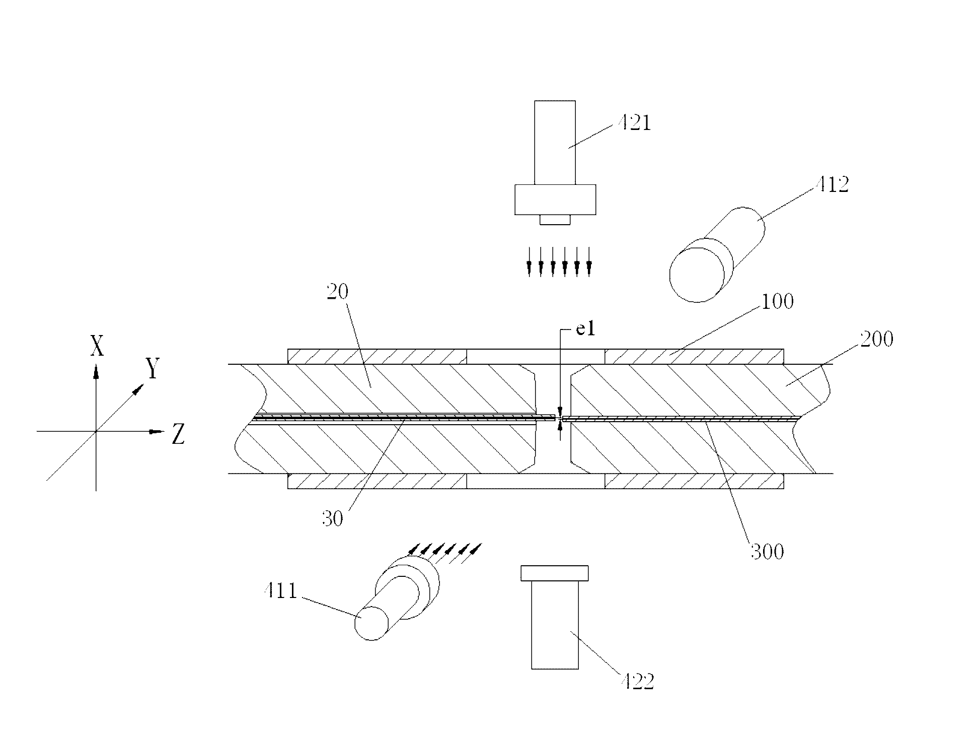
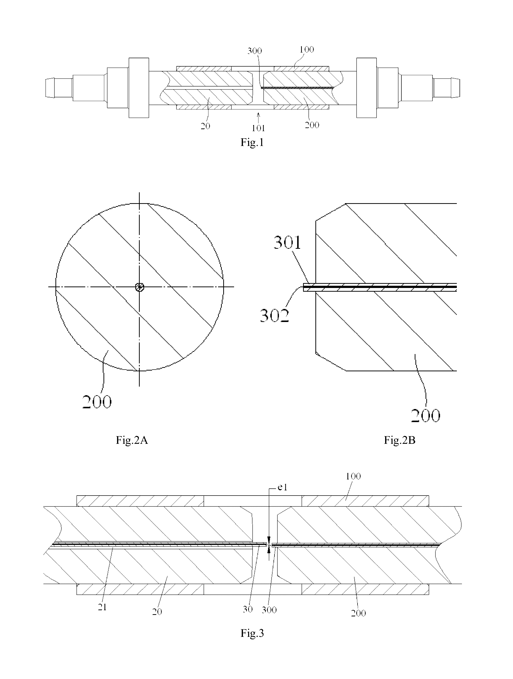
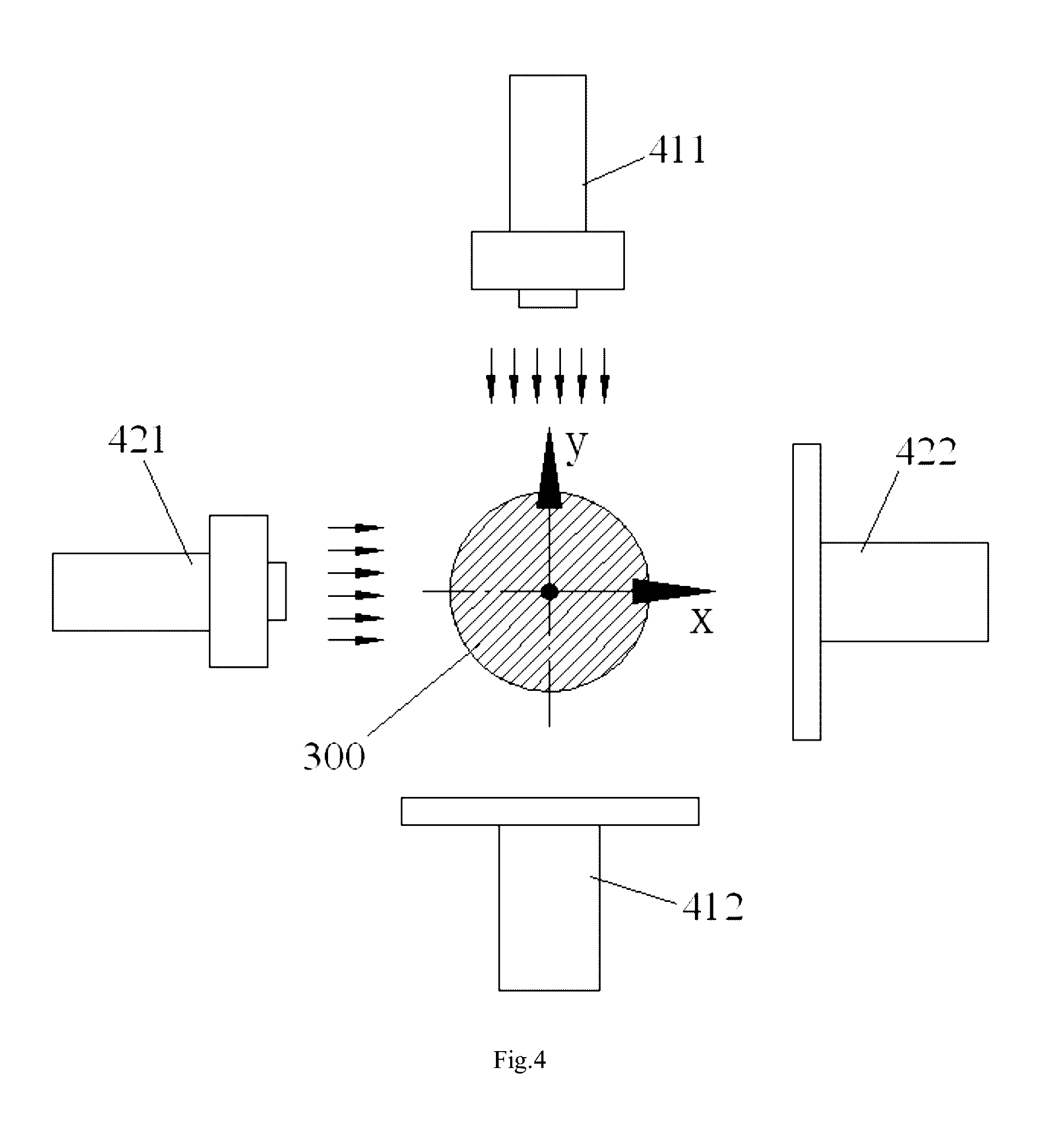
The present invention discloses an alignment system for calibrating a position of an optical fiber (30) in a bore of a ferrule (20), comprising: an outer cylinder alignment element (100) for calibrating a center position of an outer cylinder of the ferrule (20), so that the center of the outer cylinder of the ferrule (20) is aligned with a center of the outer cylinder alignment element (100); a fiber core alignment element (300) comprising a fiber core (302) having a center aligned with the center of the outer cylinder alignment element (100); an optical vision system (411, 412, 421, 422) for identifying a center position of a fiber core (32) of the optical fiber (30) and the center position of the fiber core (302) of the fiber core alignment element (300); and a controlling and moving system for actively adjusting the position of the optical fiber (30) in the bore of the ferrule (20) under the guide of the optical vision system (411, 412, 421, 422), so that the center of the fiber core (32) of the optical fiber (30) is aligned with the center of the fiber core (302) of the fiber core alignment element (300), and so that the center of the fiber core (32) of the optical fiber (30) is aligned with the center of the outer cylinder of the ferrule (20), eliminating the insertion loss of the ferrule (20) due to a radial deviation between the center of the fiber core (32) of the optical fiber (30) and the center of the outer cylinder of the ferrule (20).

Description

CROSS-REFERENCE TO RELATED APPLICATION[0001]This application claims the benefit of Chinese Patent Application No. 201410015878.2 filed on Jan. 14, 2014 in the State Intellectual Property Office of China, the whole disclosure of which is incorporated herein by reference.BACKGROUND OF THE INVENTION[0002]Field of the Invention[0003]The present invention relates to an alignment system and a method for calibrating a position of an optical fiber in a bore of a ferrule, a fiber optic ferrule assembly and a fiber optic connector manufactured by the alignment system and the calibrating method.[0004]Description of the Related Art[0005]A ferrule for a fiber optic connector is a high precision element manufactured by a precise machining technology, and the ferrule is a core component of the fiber optic connector. In prior art, steps of manufacturing the fiber optic connector generally comprises: obtaining a bare fiber by peeling an optical cable and cleaning the bare fiber; inserting the bare f...

Claims


Application Information

Patent Timeline
Patent Type & Authority Applications(United States)
IPC IPC(8): G02B6/38H04N5/247
CPCG02B6/3843H04N5/247G02B6/3874G01M11/37H04N23/90
Inventor TONG, ZHAOYANGLIU, LEILIN, LIN
Owner COMMSCOPE TELECOMM (SHANGHAI) CO LTD
Why Eureka
Try Eureka