Fuel cell system

a fuel cell and system technology, applied in the field of fuel cell systems, can solve the problems of easy discomfort of users and operation of injectors, and achieve the effects of reducing the number of times or frequency of operation, reducing noise and vibration, and facilitating hydrogen supply

Active Publication Date: 2016-12-29
TOYOTA JIDOSHA KK
View PDF4 Cites 7 Cited by
  • Summary
  • Abstract
  • Description
  • Claims
  • Application Information

AI Technical Summary

Benefits of technology

[0006](1) According to one aspect of the invention, there is provided a fuel cell system. The fuel cell system comprises a fuel cell stack that has a plurality of fuel cells, wherein each fuel cell includes an electrolyte membrane, an anode formed on one surface of the electrolyte membrane and a cathode formed on the other surface of the electrolyte membrane; an injector that is configured to supply hydrogen to the anode; and a controller that is configured to control operation of the injection to make a pressure of the anode reach a target pressure. In a non-power generation state that is after a start of the fuel cell system but is before power generation of the fuel cells, the controller sets a second target pressure that is higher than a first target pressure to the target pressure and controls operation of the injector to make the pressure of the anode equal to the second target pressure. After the pressure of the anode is increased to be higher than the first target pressure, the controller sets the first target pressure to the target pressure and controls operation of the injector to make the pressure of the anode equal to the first target pressure. The first target pressure is a pressure required to supply hydrogen over the entire anodes in the fuel cell stack. The fuel cell system of this aspect sets the second target pressure that is higher than the first target pressure to the target pressure of the anode, and controls operation of the injector to make the pressure of the anode equal to the second target pressure. After the pressure of the anode is increased to be higher than the first target pressure, the fuel cell system sets the first target pressure to the target pressure of the anode. This reduces the frequency when the pressure of the anode becomes lower than the first target pressure. This results in reducing the number of times or frequency of operation of the injector for the purpose of making the pressure of the anode equal to the first target pressure. This accordingly reduces the noise and the vibration caused by operation of the injection in the non-power generation state.
[0007](2) The fuel cell system of the above aspect may further comprise a circulation passage that is arranged to return an off gas discharged from the anode, to the anode; and a pump that is provided on the circulation passage. The controller may operate the pump to return the off gas discharged from the anode, to the anode in the non-power generation state. The fuel cell system of this aspect makes it, easier to supply hydrogen over the entire anode in the fuel cell and thus more effectively suppresses hydrogen deficiency in the anode.
[0008](3) In the fuel cell system of the above aspect, in the non-power generation state, after making the pressure of the anode equal to the second target pressure, the controller may measure the pressure of the anode to perform a hydrogen leakage test in the fuel cell system. The fuel cell system of this aspect reduces the noise and the vibration caused by operation of the injector in the configuration that performs the hydrogen leakage test.

Problems solved by technology

In such a fuel cell system using the injector to regulate the supply amount of the fuel gas, in a non-power generation state where neither a compressor configured to supply the air used for power generation of the fuel cell nor a cooling water pump configured to circulate cooling water for the fuel cell starts operating after a start of the system, operation of the injector, especially frequent operation of the injector, is likely to make the user feel uncomfortable because of the lack of operation noise of the compressor and the cooling water pump, compared with the operation of the injector in the power generation state.

Method used


Image

  • Fuel cell system
  • Fuel cell system
  • Fuel cell system

Examples


first embodiment

A. First Embodiment

[0017]A1. System Configuration

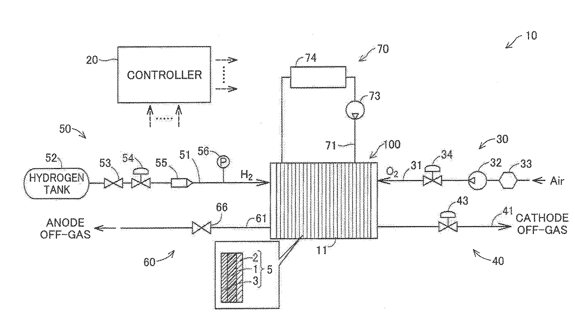
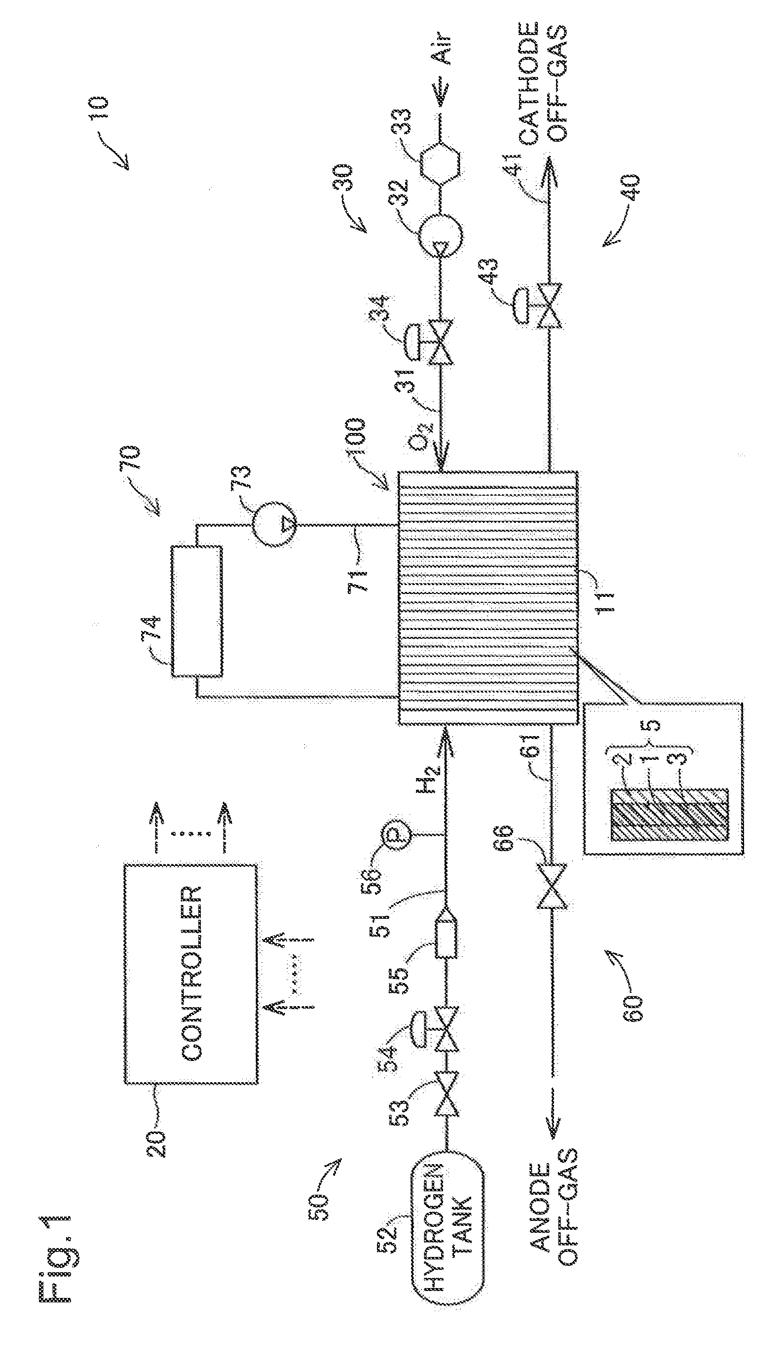
[0018]FIG. 1 is a diagram illustrating the schematic configuration of a fuel cell system 10 according to a first embodiment of the invention. The fuel cell system 10 is mounted on, for example, a vehicle to output electric power as the power source of the vehicle in response to the driver's request. The fuel cell system 10 of the embodiment includes a fuel cell stack 100, a controller 20, a cathode gas supply system 30, a cathode gas discharge system 40, an anode gas supply system 50, an anode gas discharge system 60 and a cooling system 70.

[0019]The fuel cell stack 100 is implemented by polymer electrolyte fuel cells that receive supplies of hydrogen (anode gas) and the air (cathode gas) as reactive gases and generate electric power. The fuel cell stack 100 is constituted by stacking a plurality of fuel cells 11.

[0020]Each fuel cell 11 includes a membrane electrode assembly 5, and two separators (not shown) that are plate base member...

second embodiment

B. Second Embodiment

[0052]B1. System Configuration

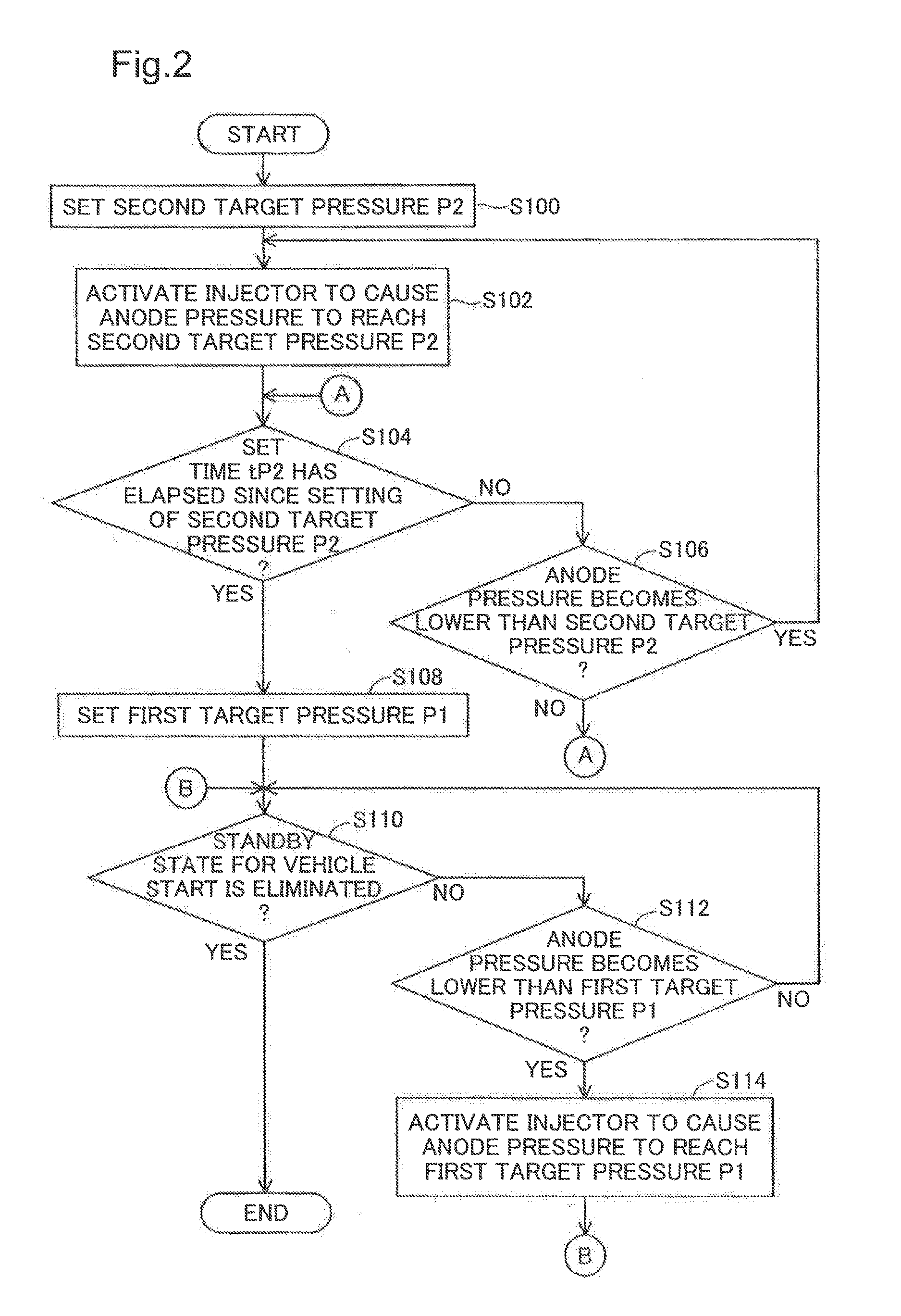
[0053]The fuel cell system 10 of the first embodiment suppresses deterioration of the fuel cell stack 100 caused by deficiency of hydrogen in the anodes, while reducing the noise and the vibration caused by the operation of the injector 55 in the non-power generation state that is after a start of the fuel cell system 10 but is before power generation of the fuel cell stack 100. A second embodiment, on the other hand, describes a fuel cell system 10a that includes an anode gas circulation system 80 configured to circulate an anode off-gas discharged from the anodes to the fuel cell stack 100 and thereby more effectively suppresses deterioration of the fuel cell stack 100 caused by deficiency of hydrogen in the anodes.

[0054]FIG. 4 is a diagram illustrating the schematic configuration of the fuel cell system 10a according to the second embodiment. The fuel cell system 10a of this embodiment includes the fuel cell stack 100, the control...

third embodiment

C. Third Embodiment

[0065]C1. System Configuration

[0066]The fuel cell systems 10 and 10a of the first and the second embodiments reduce the noise and the vibration caused by the operation of the injector 55, while supplying hydrogen to the fuel cell stack 100 in the non-power generation state, in order to save the time period until hydrogen is actually supplied to the fuel cell stack 100 at the start of power generation of the fuel cells 11. A third embodiment, on the other hand, describes a fuel cell system that is configured to suppress the noise and the vibration caused by the operation of the injector 55 while supplying hydrogen to the fuel cell stack 100 to perform a hydrogen leakage test in the non-power generation state of the fuel cell stack 100. In the non-power generation state, after making the anode pressure equal to the second target pressure P2, the controller 20 measures the anode pressure to perform the hydrogen leakage test. The schematic configuration of the fuel ce...


PUM

PropertyMeasurementUnit
pressureaaaaaaaaaa
frequencyaaaaaaaaaa
noiseaaaaaaaaaa

Abstract

An object is to reduce the noise and the vibration caused in operation of an injector in a non-power generation state of a fuel cell. There is provided a fuel cell system comprising fuel cells configured such that each fuel cell includes an anode, an electrolyte membrane and a cathode; an injector that is configured to supply hydrogen to the anode; and a controller that is configured to control operation of an injector to make pressure of the anode reach a target pressure. In a non-power generation state that is after a start of the fuel cell system but is before power generation of the fuel cells, the controller sets a second target pressure that is higher than a first target pressure to the target pressure and controls operation of the injector to make the pressure of the anode equal to the second target pressure. After the pressure of the anode is increased to be higher than the first target pressure, the controller sets the first target pressure to the target pressure and controls operation of the injector to make the pressure of the anode equal to the first target pressure. The first target pressure is a pressure required to supply hydrogen over the entire anodes in the fuel cell stack.

Description

CROSS-REFERENCE TO RELATED APPLICATIONS[0001]The present application claims priority from Japanese patent application No. 2015-127344 filed on Jun. 25, 2015, the content of which is hereby incorporated by reference into this application.BACKGROUNDField[0002]The present invention relates to a fuel cell system.Related Art[0003]As an example of a fuel cell system that controls the supply of a reactive gas to a fuel cell, a system disclosed in JP 2008-130442A computes a target pressure value of a fuel gas based on the operating state of a fuel cell stack and controls operation of the injector to regulate the supply amount of the fuel gas, in order to compensate for a difference between the calculated target pressure value and a pressure value detected by a sensor.[0004]In such a fuel cell system using the injector to regulate the supply amount of the fuel gas, in a non-power generation state where neither a compressor configured to supply the air used for power generation of the fuel ce...

Claims


Application Information

Patent Timeline
Patent Type & Authority Applications(United States)
IPC IPC(8): H01M8/04225H01M8/04029H01M8/2457H01M8/04111H01M8/04089H01M8/241
CPCH01M8/04225H01M8/04089H01M8/241H01M2250/20H01M8/04111H01M8/04029H01M8/2457H01M8/04753H01M8/04097H01M8/04388H01M8/04664H01M8/04302Y02E60/50Y02T90/40H01M8/04679H01M8/04776H01M2008/1095
Inventor OKUYOSHI, MASAHIROIMANISHI, HIROYUKIYAMAMOTO, KAZUO
Owner TOYOTA JIDOSHA KK
Why Eureka
Try Eureka