Stereoscopic 3D projection system with improved level of optical light efficiency

a projection system and optical light efficiency technology, applied in the field of stereoscopic 3d projection system, can solve the problems of reducing the overall optical light efficiency of the system, generating stereoscopic 3d images that are severely lacking in on-screen image brightness, and less than approximately 90%, so as to reduce the level of ghosting or crosstalk and reduce the overall on-screen image brightness

Active Publication Date: 2016-12-29
VOLFONI R&D EURL
View PDF0 Cites 16 Cited by
  • Summary
  • Abstract
  • Description
  • Claims
  • Application Information

AI Technical Summary

Benefits of technology

[0036]An object of the present invention is to provide a method to reduce the level of ghosting or crosstalk when viewing time-multiplexed stereoscopic 3d images using a multiple-beam system comprising of two or more separate image-beams without the necessity of utilizing a polarization rotator placed within the optical-path of at least one of said primary and secondary image-beams and which would otherwise reduce the overall on-screen image brightness.
[0037]A further object of the present invention is to provide a triple-beam stereoscopic 3d projection system comprising a polarization modulator for each of said primary and secondary image-beams, with said polarization modulators each further comprising a stack of two individual pi-cells oriented in mutually crossed orientation and which generates a low level of ghosting or crosstalk whilst maintaining a higher level of optical efficiency as compared to other prior-art technologies.
[0038]The invention is based on the insight that when the linear polarization state of an image-beam at the input surface of a polarization modulator comprising a stack of two individual pi-cells is parallel with the linear polarization-filter present in at least one of the lenses of said passive circular-polarized viewing-goggles, then a high level of optical blocking can still be achieved for one of said lenses by incorporating a suitable contrast enhancement film comprising a stack of three or more uniaxially stretched in-plane retardation-films located at the exit surface of said polarization modulator and designed so as to perturb and improve the level of circular polarization of the image-beam exiting said polarization modulator without changing the overall circular polarization state of said image-beam in order to increase the amount of optical blocking achieved by said lens, thereby reducing the level of ghosting or crosstalk whilst maintaining the overall optical light efficiency at a high level.

Problems solved by technology

However, one problem of the aforementioned single-beam system according to the state of the art is that since images generated by typical 3-chip DLP digital cinema projectors are initially randomly polarized, then the linear polarization-filter located at the input surface of said polarization modulator will absorb approximately 50% of the incoming light generated by said projector.
This will therefore significantly reduce the overall optical light efficiency of the system, thereby resulting in the creation of stereoscopic 3d images that are severely lacking in on-screen image brightness.
Whilst the use of a polarization rotator to rotate by 90 degrees the linear polarization state of the secondary image-beam ensures the system possesses a low level of ghosting or crosstalk when viewing stereoscopic 3d images according to the state of the art, the optical efficiency of said polarization rotator is typically less than approximately 90% over the visible wavelength range, thereby resulting in a loss of optical light efficiency and a reduction in the overall on-screen image brightness.
The double-beam system described above in the aforementioned U.S. Pat. No. 8,220,934 B2 according to the state of the art also has the disadvantage in that there is a relatively large optical-path-length difference between said primary and secondary image-beams, thereby typically requiring the use of a telephoto-lens pair and / or the deformation of the reflecting-mirror in order to compensate for said optical-path-length difference.
However this will add both complexity and expense to the overall system.
Furthermore, since the linear polarization states of said primary and secondary image-beams are mutually orthogonal, it will be understood by one skilled in the art that the linear polarization state of at least one of said primary and secondary image-beams will be parallel with the transmission axis of the linear polarization-filters present in the lenses of said passive circular-polarized viewing-goggles and in this disadvantageous configuration according to the state of the art there will normally be an undesirably high level of ghosting or crosstalk when viewing time-multiplexed stereoscopic 3d images.
However, since the optical efficiency of said polarization rotator is typically less than approximately 90% over the visible wavelength region, this will generate an unwanted loss of optical light efficiency and reduce the overall on-screen image brightness.

Method used


Image

  • Stereoscopic 3D projection system with improved level of optical light efficiency
  • Stereoscopic 3D projection system with improved level of optical light efficiency
  • Stereoscopic 3D projection system with improved level of optical light efficiency

Examples


Embodiment Construction

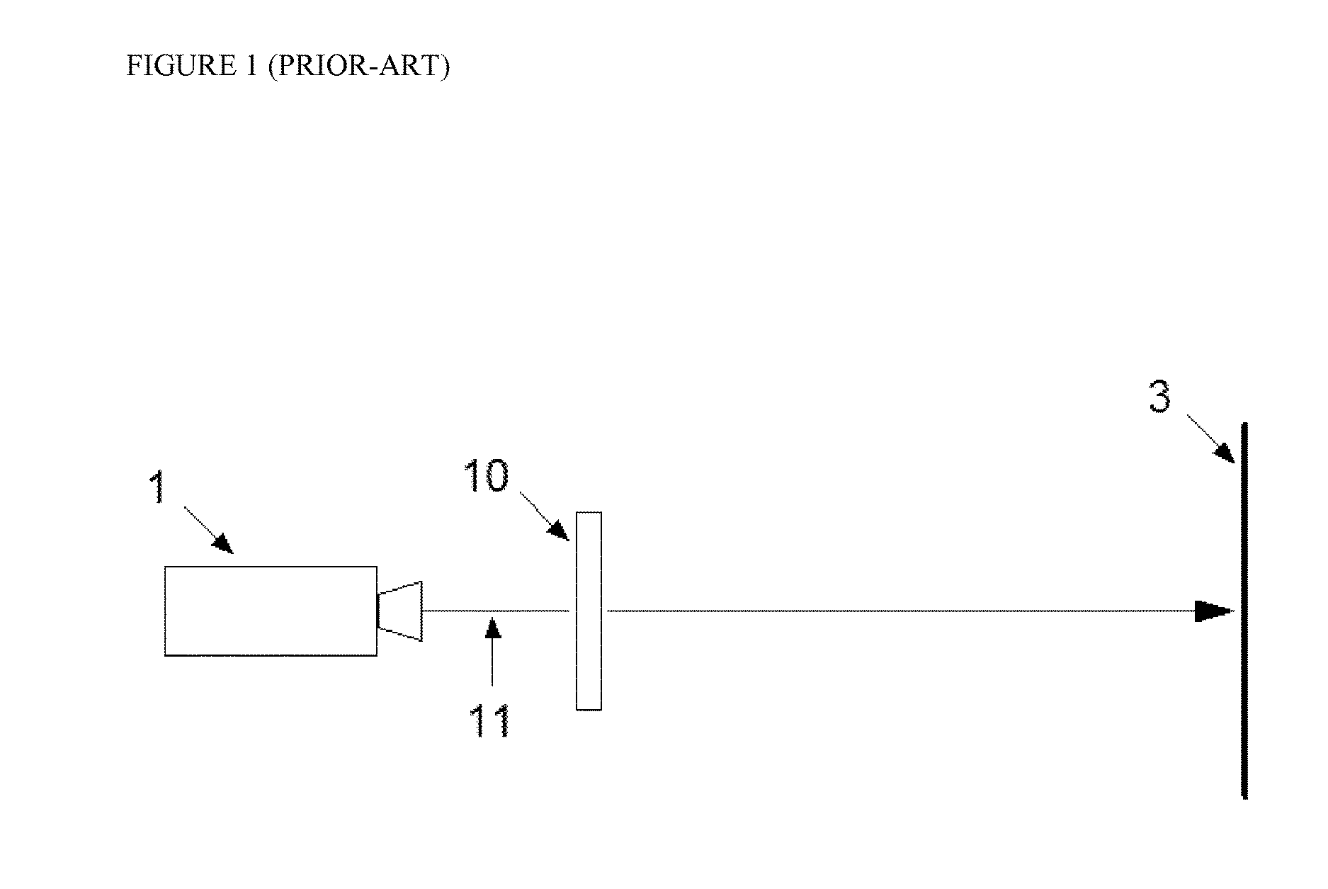
[0050]FIG. 1 shows a single-beam stereoscopic 3d projection system according to the state of the art where a polarization modulator 10 comprising a stack of one or more liquid crystal elements (not shown) is placed directly in front of the lens of a projector 1, such as a 3-chip DLP digital cinema projector or otherwise.

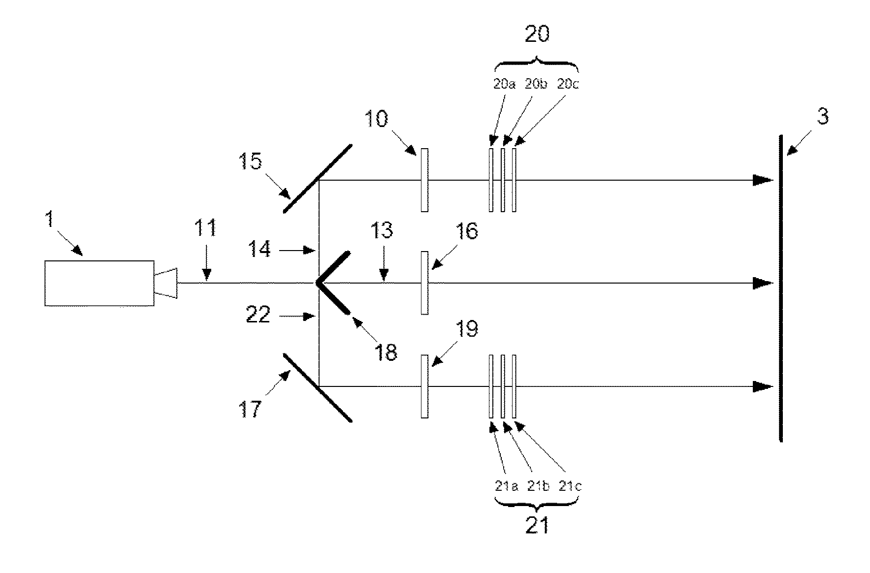
[0051]In this figure and all underlying figures thereafter, the paths of image-beams are represented by single-line vectors for ease of clarity. However, it will be understood by one skilled in the art that said image-beams typically possess some level of angular divergence, for example ±10 degrees in the vertical plane and ±22 degrees in the horizontal plane, respectively. However, it is to be understood that the occurrence of said beam divergence does not depart from the inventive ideas disclosed herein and will therefore be omitted in the underlying drawings for ease of clarity.

[0052]The projector 1 generates a succession of alternate left and right-eye images 11 ...


PUM


Abstract

A time-multiplexed stereoscopic 3d projection system including a beam-splitting element to split the randomly polarized image-beam generated by a single-lens projector into one primary image-beam, possessing a first state of linear polarization, and two secondary image-beams, both possessing a second state of linear polarization. The polarization states are mutually orthogonal. The primary and secondary image-beams recombine to form a complete image on the surface of a polarization-preserving projection-screen. There are polarization modulators that modulate the first and second states of linear polarization between a left and right circular polarization state. There is a contrast enhancement film in the optical-path of the primary or secondary image-beams located between the polarization modulator and the projection-screen. The contrast enhancement film comprises a stack of at least three uniaxially stretched retardation-films which perturb the circular polarization state of said image-beams and which possess an in-plane retardation value substantially equal to 140 nm, 270 nm, or 540 nm.

Description

FIELD OF INVENTION[0001]The present invention relates to a stereoscopic 3d projection system offering an improved level of optical light efficiency and designed to provide time-multiplexed stereoscopic 3d images using a single-lens projector together with a polarization beam-splitter, polarization modulator, silver-screen and passive circular-polarized viewing-goggles.BACKGROUND[0002]Stereoscopic 3d projection systems have been used for many years. One technology known to the art and described for example in US patent no. 2006 / 0291053A1 dated 28 Dec. 2006 and entitled “Achromatic Polarization Switches”, describes how a polarization modulator can be placed in-front of a single-lens projector such as a 3-chip DLP digital cinema projector.[0003]The projector is arranged so as to generate a single-beam comprising a succession of alternate left and right-eye images at high speeds of typically 144 Hz. The polarization modulator then imparts an optical polarization state to images generate...

Claims


Application Information

Patent Timeline
Patent Type & Authority Applications(United States)
IPC IPC(8): H04N13/04G03B21/56G02B27/28G02B5/30G02B30/25H04N13/363
CPCH04N13/0434H04N13/0438G02B5/3083G02B5/3041G02F1/13363H04N13/0459G02B27/283G02B27/26G03B21/56H04N13/363H04N13/337H04N13/341G02B30/24G02B30/25
Inventor PALMER, STEPHEN
Owner VOLFONI R&D EURL
Why Eureka
Try Eureka