Bicycle control system
a control system and bicycle technology, applied in the direction of bicycle equipment, chain/belt transmission, vehicle components, etc., to achieve the effect of increasing and reducing the torque of the assist motor
- Summary
- Abstract
- Description
- Claims
- Application Information
AI Technical Summary
Benefits of technology
Problems solved by technology
Method used
Image
Examples
first embodiment
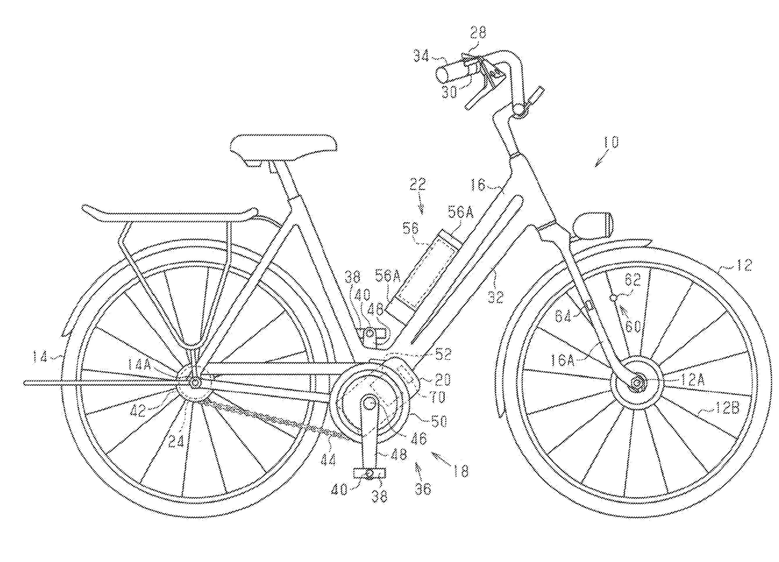
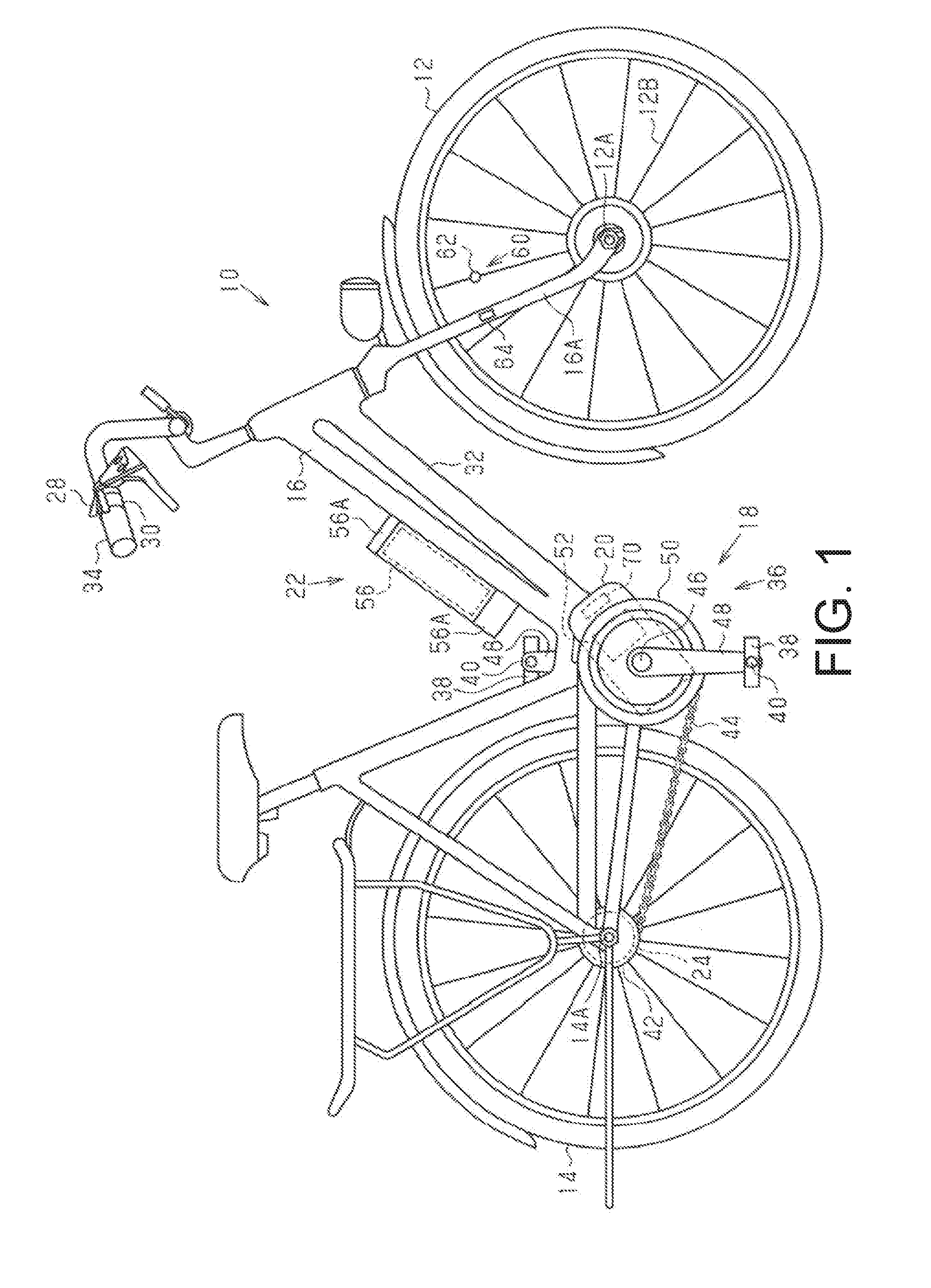
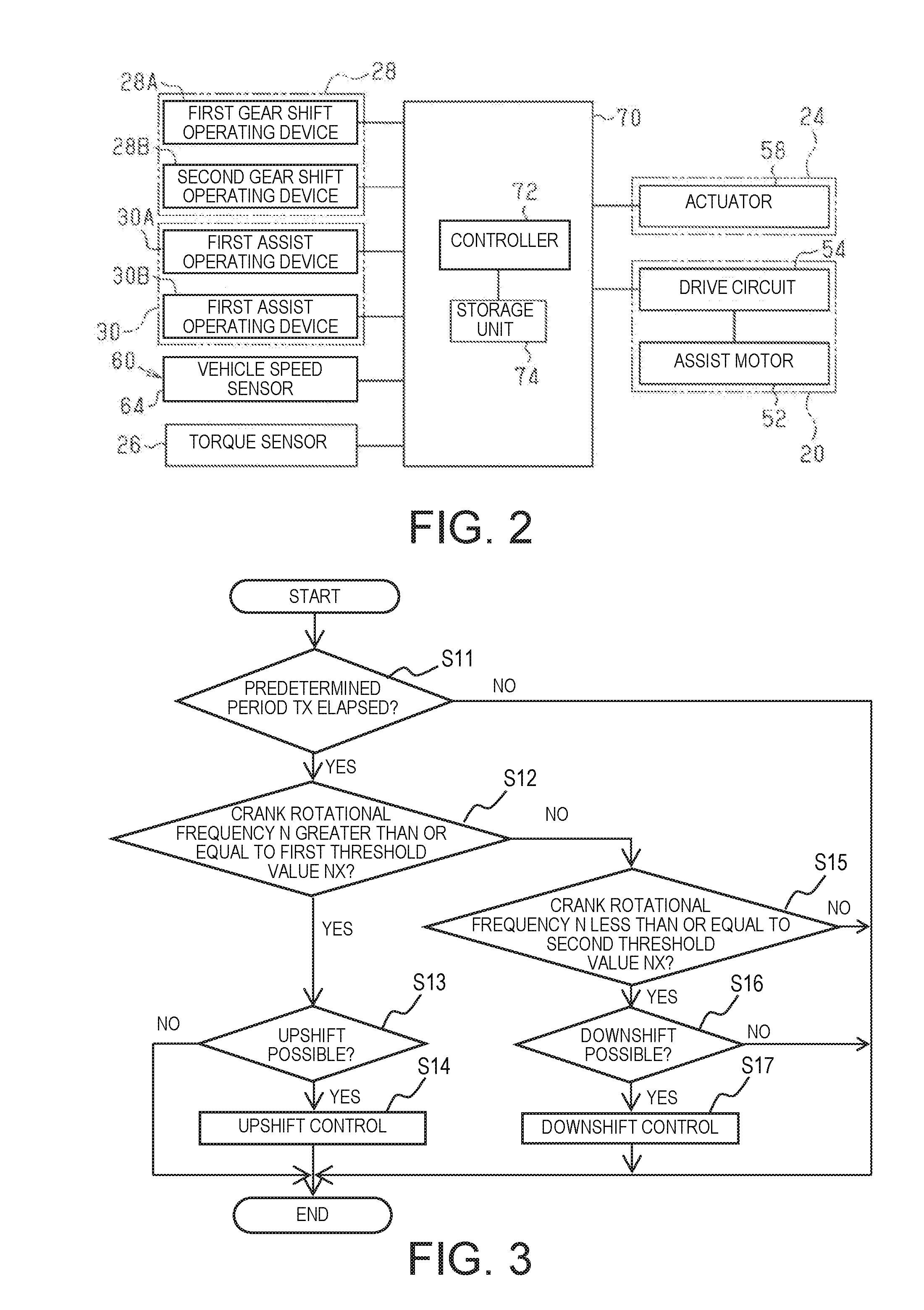
[0041]Referring initially to FIG. 1, a configuration of a bicycle 10 is illustrated that is equipped with a bicycle control system in accordance with selected illustrated embodiments. The bicycle 10 comprises a front wheel 12, a rear wheel 14, a vehicle body 16, a drive mechanism 18, an assist mechanism 20, a battery unit 22, an electric transmission 24, a torque sensor 26 (refer to FIG. 2), a gear shift operating unit 28, an assist operating unit 30 and a bicycle control system 70. The electric transmission 24 is a bicycle component.
[0042]The vehicle body 16 comprises a frame 32, a handlebar 34 and a front fork 16A. The handlebar 26 is detachably connected to the frame 32. The front fork 16A is connected to the frame 32. The front fork 16A is supported to the frame 32 and connects the handlebar 34 and an axle 12A of the front wheel 12.
[0043]The drive mechanism 18 comprises a crank assembly 36, a pair of (left and right) pedals 38, a pair of (left and right) pedal shafts 40, a rear ...
second embodiment
[0090]The second embodiment of the bicycle control apparatus will be described, with reference to FIGS. 6 to 8. The portions that are common to the first embodiment are given the same codes, and the descriptions thereof will be omitted.
[0091]As shown in FIG. 7, the first value NX and the second value NY are set for each gear shift stage. The first value NX and the second value NY are set to be increased as the gear shift stage is increased, that is, as the gear ratio γ is increased.
[0092]A change amount F of the threshold value corresponding to each gear shift stage is stored in the storage unit 74. The difference in the change amount F of the threshold value between adjacent gear shift stages shall be difference G. Difference G can be configured to be settable by one or both of the operating units 28 and 30 or by an external device. For example, difference G is selected to 5. In this case, for example, in a transmission 24 having gear shift stages from the first stage to the eighth...
third embodiment
[0101]The third embodiment of the bicycle control apparatus will be described, with reference to FIGS. 9 to 10. The portions that are common to the first embodiment are given the same codes, and the descriptions thereof will be omitted. In the present embodiment, the assist motor 52 is a bicycle component. Further, the traveling load R is a parameter representing the running state of the bicycle 10. In addition, the assist operating unit 30 is an operating unit, the first assist operating device 30A is the first operating unit, and the second assist operating device 30B is the second operating unit.
[0102]The controller 72 controls the electric transmission 24 based on a threshold value and the traveling load R. The threshold value includes a first value RX, and a second value RY that is smaller than the first value RX. The controller 72 changes the control mode of the assist mechanism 20 based on a comparison result between the traveling load R and the first value RX as well as the ...
PUM
 Abstract
Description
Claims
Application Information
 - R&D
- Intellectual Property
- Life Sciences
- Materials
- Tech Scout
- Unparalleled Data Quality
- Higher Quality Content
- 60% Fewer Hallucinations
Browse by: Latest US Patents, China's latest patents, Technical Efficacy Thesaurus, Application Domain, Technology Topic, Popular Technical Reports.
© 2025 PatSnap. All rights reserved.Legal|Privacy policy|Modern Slavery Act Transparency Statement|Sitemap|About US| Contact US: help@patsnap.com


