Solar Thermal Power Generation System and Solar Thermal Power Generation Method

a solar thermal and power generation system technology, applied in the direction of steam generation using solar heat, steam generation using hot heat carriers, lighting and heating apparatus, etc., can solve the problems of increasing the construction cost of the solar thermal power generation system, structurally difficult separation of the inside of the tank and the lower part by the heat insulating member, etc., to achieve efficient use of solar heat collected, simplified solar heat storage/release system, and reduced construction cost

Active Publication Date: 2017-01-05
MITSUBISHI POWER LTD
View PDF7 Cites 9 Cited by
  • Summary
  • Abstract
  • Description
  • Claims
  • Application Information

AI Technical Summary

Benefits of technology

[0008]According to the present invention, the steam turbine is driven with part of the superheated steam generated by solar heat and thereby generates electric power. Further, by the heat exchange in the heat storage heater between the rest of the superheated steam and the heat storage medium from the low-temperature tank, sensible heat of the superheated steam is stored in the heat storage medium while satu

Problems solved by technology

In cases where a great amount of heat storage medium has to be contained, separating the inside of the tank into the upper part and the lower part by the heat insulating member is supposed to be structurally difficult

Method used


Image

  • Solar Thermal Power Generation System and Solar Thermal Power Generation Method
  • Solar Thermal Power Generation System and Solar Thermal Power Generation Method
  • Solar Thermal Power Generation System and Solar Thermal Power Generation Method

Examples


embodiment

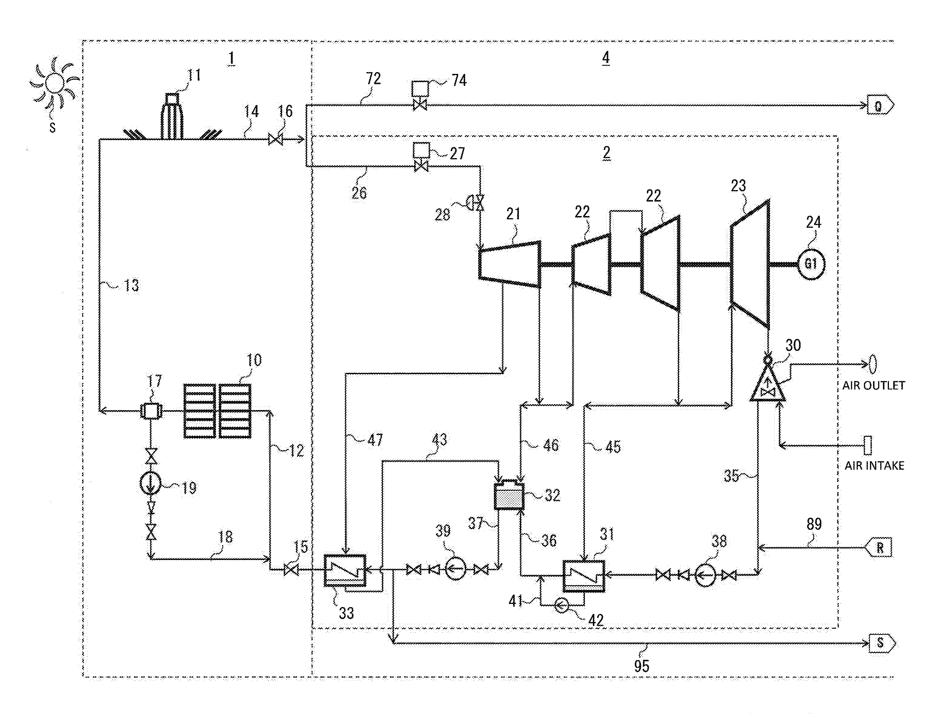
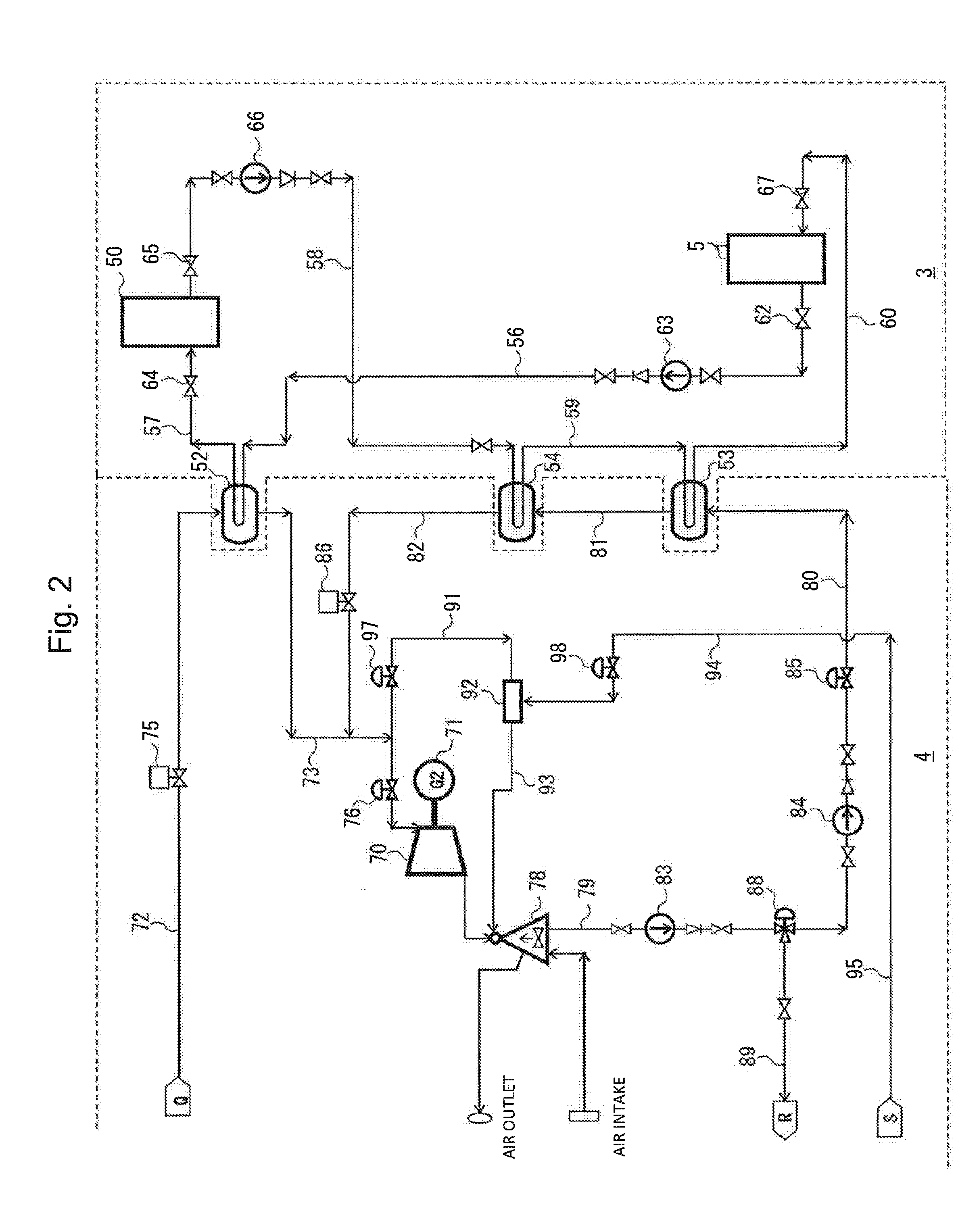
[0019]First, a system configuration of a solar thermal power generation system and a solar thermal power generation method according to an embodiment of the present invention will be described below with reference to FIGS. 1 and 2.

[0020]FIG. 1 is a configuration diagram showing a solar heat collection system and a main power generation system constituting part of the solar thermal power generation system according to the embodiment of the present invention. FIG. 2 is a configuration diagram showing a solar heat storage / release system and a secondary power generation system constituting the other part of the solar thermal power generation system according to the embodiment of the present invention. In FIG. 1, arrows indicate the flow of a heat medium (water / steam) of the solar thermal power generation system. In FIG. 2, arrows indicate the flow of a heat medium (water / steam) or a heat storage medium (molten salt) of the solar thermal power generation system. In FIGS. 1 and 2, the ref...


PUM


Abstract

a solar thermal power generation system includes a solar heat collection system that generates superheated steam by solar heat, a main power generation system that performs power generation by part of the superheated steam generated by the solar heat collection system, a solar heat storage/release system that stores heat in a heat storage medium or releases the heat stored in the heat storage medium, and a secondary power generation system that performs power generation by saturated steam generated by the heat storage or the heat release in the solar heat storage/release system. The solar heat storage/release system includes a heat storage heater for exchanging heat between the rest of the superheated steam generated by the solar heat collection system and the heat storage medium to store heat in the heat storage medium and to generate saturated steam, a low-temperature tank for containing the heat storage medium to be supplied to the heat storage heater, and a high-temperature tank for containing the heat storage medium after the heat storage in the heat storage heater. The secondary power generation system includes a saturated steam turbine into which the saturated steam generated by the heat storage heater can be introduced.

Description

BACKGROUND OF THE INVENTION1. Field of the Invention[0001]The present invention relates to a solar thermal power generation system and a solar thermal power generation method, and in particular, to a solar thermal power generation system including a heat storage system capable of storing solar heat and releasing of the stored solar heat, and a method of power generation by the power generation system.2. Description of the Related Art[0002]There exist solar thermal power generation systems capable of performing power generation by collecting solar heat while storing the collected solar heat and also capable of performing power generation by releasing the stored solar heat. JP-2014-92086-A discloses a solar thermal power generation system (solar thermal power generation plant) designed to simplify the heat medium cycle of the whole power generation system by integrating a heat medium cycle for collecting the solar heat and a heat medium cycle for driving a steam turbine together. For ...

Claims


Application Information

Patent Timeline
IPC IPC(8): F03G6/00F24J2/34F24S10/70
CPCF24S60/00F01D15/10F01K19/00F22B1/06F03G6/065F01K7/165Y02E10/46F01K3/06F22B1/006F03G6/003F24S60/30Y02E60/14
Inventor MISHIMA, NOBUYOSHINAGAFUCHI, NAOYUKI
Owner MITSUBISHI POWER LTD
Why Eureka
Try Eureka