Diffractive optical elements with asymmetric profiles

a technology asymmetric profiles, applied in the field of diffractive optical elements with asymmetric profiles, can solve the problems of less optimal optical properties and more pronounced banding of bands, and achieve the effects of reducing “banding” and minimizing system weigh

Active Publication Date: 2017-01-05
MICROSOFT TECH LICENSING LLC
View PDF10 Cites 100 Cited by
  • Summary
  • Abstract
  • Description
  • Claims
  • Application Information

AI Technical Summary

Benefits of technology

[0002]In an optical display system that includes a waveguide with multiple diffractive optical elements (DOEs), gratings in one or more of the DOEs may have an asymmetric profile in which gratings are slanted (i.e., walls of the grating are non-orthogonal to the plane of the waveguide) or blazed. Asymmetric gratings in a DOE can provide increased display uniformity in the optical display system by reducing the “banding” resulting from optical interference that is manifested as dark stripes in the disp

Problems solved by technology

Banding may be more pronounced when polymeric materials are used in volume production of the DOEs to minimiz

Method used


Image

  • Diffractive optical elements with asymmetric profiles
  • Diffractive optical elements with asymmetric profiles
  • Diffractive optical elements with asymmetric profiles

Examples


Embodiment Construction

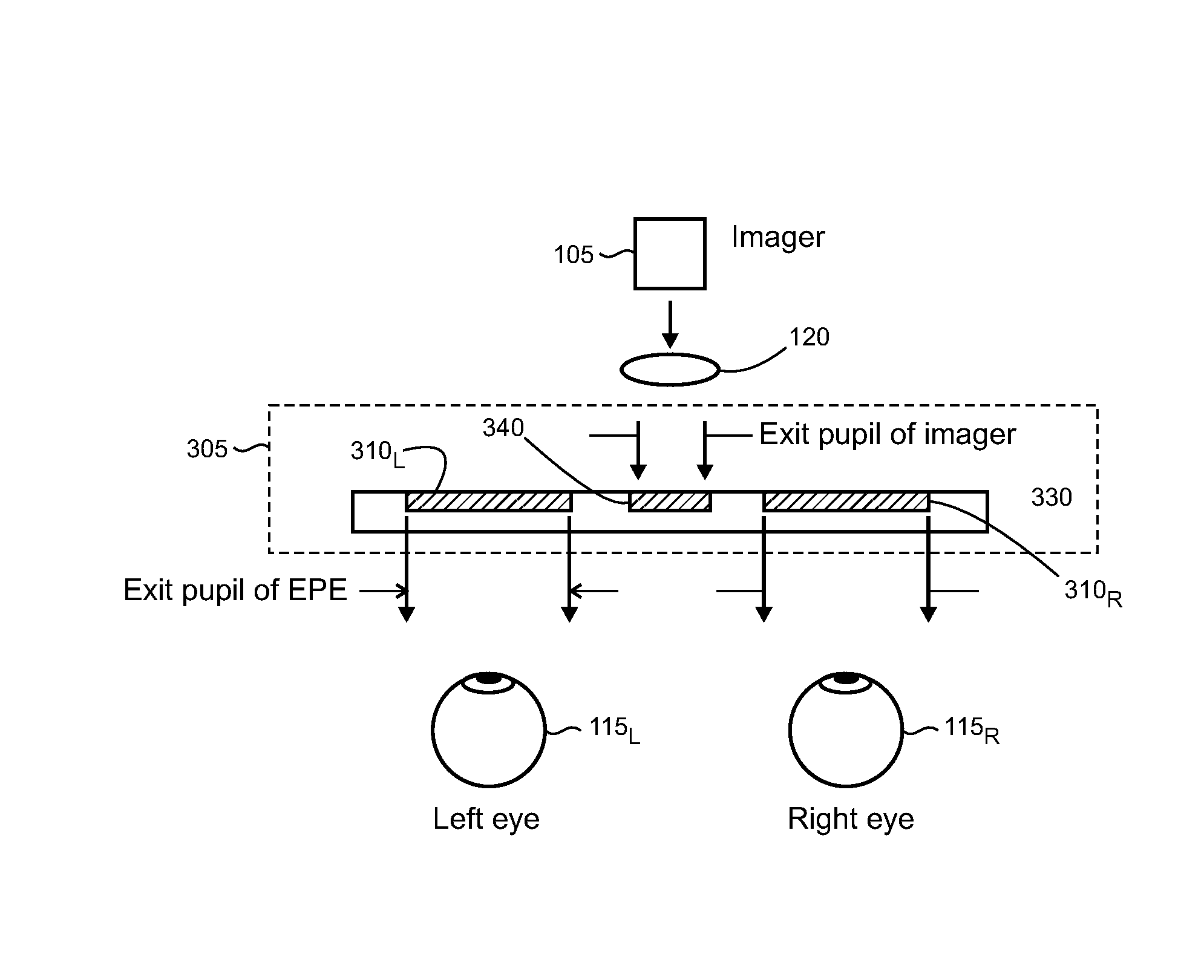
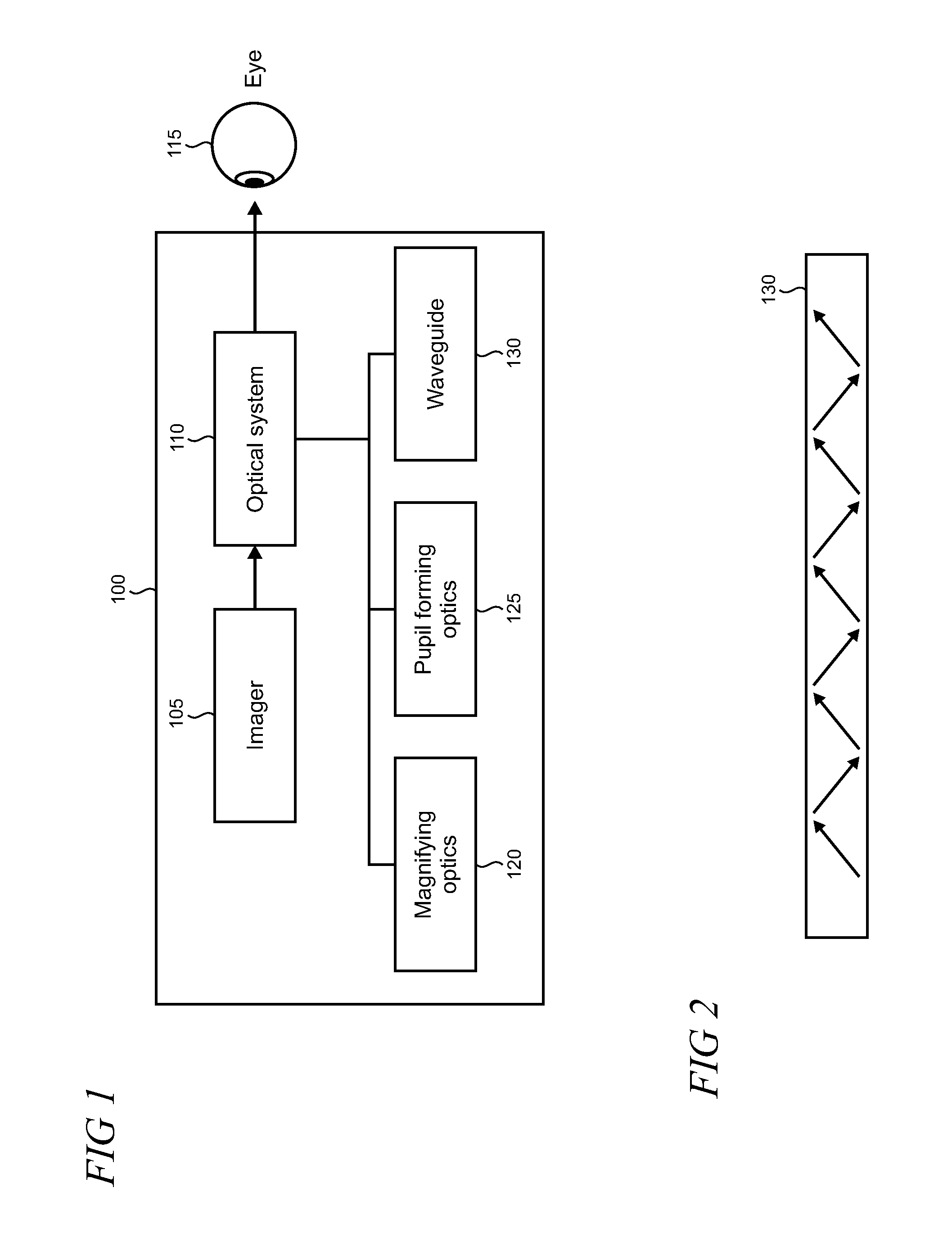
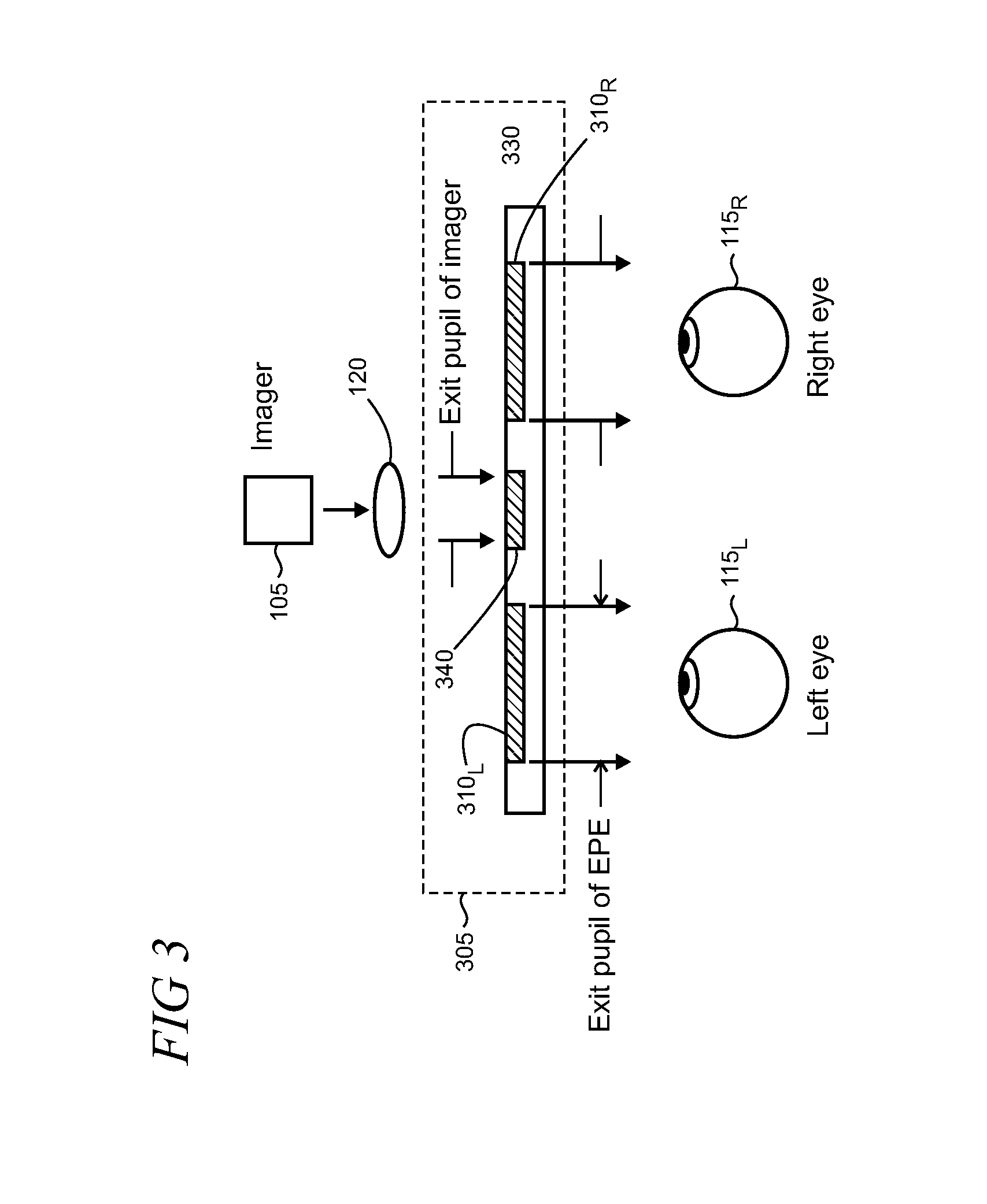
[0018]FIG. 1 shows a block diagram of an illustrative near eye display system 100 which may incorporate diffractive optical elements (DOEs) with asymmetric profiles. Near eye display systems are frequently used, for example, in head mounted display (HMD) devices in industrial, commercial, and consumer applications. Other devices and systems may also use DOEs with asymmetric profiles, as described below, and it is emphasized that the near eye display system 100 is intended to be an example that is used to illustrate various features and aspects, and the present DOEs are not necessarily limited to near eye display systems.

[0019]System 100 may include an imager 105 that works with an optical system 110 to deliver images as a virtual display to a user's eye 115. The imager 105 may include, for example, RGB (red, green, blue) light emitting diodes (LEDs), LCOS (liquid crystal on silicon) devices, OLED (organic light emitting diode) arrays, MEMS (micro-electro mechanical system) devices, ...


PUM


Abstract

In an optical display system that includes a waveguide with multiple diffractive optical elements (DOEs), gratings in one or more of the DOEs may have an asymmetric profile in which gratings may be slanted or blazed. Asymmetric gratings in a DOE can provide increased display uniformity in the optical display system by reducing the “banding” resulting from optical interference that is manifested as dark stripes in the display. Banding may be more pronounced when polymeric materials are used in volume production of the DOEs to minimize system weight, but which have less optimal optical properties compared with other materials such as glass. The asymmetric gratings can further enable the optical system to be more tolerant to variations—such as variations in thickness, surface roughness, and grating geometry—that may not be readily controlled during manufacturing particularly since such variations are in the submicron range.

Description

BACKGROUND[0001]Diffractive optical elements (DOEs) are optical elements with a periodic structure that are commonly utilized in applications ranging from bio-technology, material processing, sensing, and testing to technical optics and optical metrology. By incorporating DOEs in an optical field of a laser or emissive display, for example, the light's “shape” can be controlled and changed flexibly according to application needs.SUMMARY[0002]In an optical display system that includes a waveguide with multiple diffractive optical elements (DOEs), gratings in one or more of the DOEs may have an asymmetric profile in which gratings are slanted (i.e., walls of the grating are non-orthogonal to the plane of the waveguide) or blazed. Asymmetric gratings in a DOE can provide increased display uniformity in the optical display system by reducing the “banding” resulting from optical interference that is manifested as dark stripes in the display. Banding may be more pronounced when polymeric ...

Claims


Application Information

Patent Timeline
IPC IPC(8): G02B27/01G02B27/42G02B27/00G02B5/18
CPCG02B27/0081G02B27/4205G02B27/4272G02B2027/0178G02B2027/0112G02B27/0172G02B5/1819G02B5/1852G02B27/0101
Inventor VALLIUS, TUOMASSAINIEMI, LAURI
Owner MICROSOFT TECH LICENSING LLC
Why Eureka
Try Eureka