

Database management system, computer, and database management method
a database management system and database technology, applied in the field of data input/output, can solve the problem of enormous time spent on the search of specific data from de data, and achieve the effect of improving the performance of the database management system
- Summary
- Abstract
- Description
- Claims
- Application Information
AI Technical Summary
Benefits of technology
Problems solved by technology
Method used
Image

Examples
embodiment 1
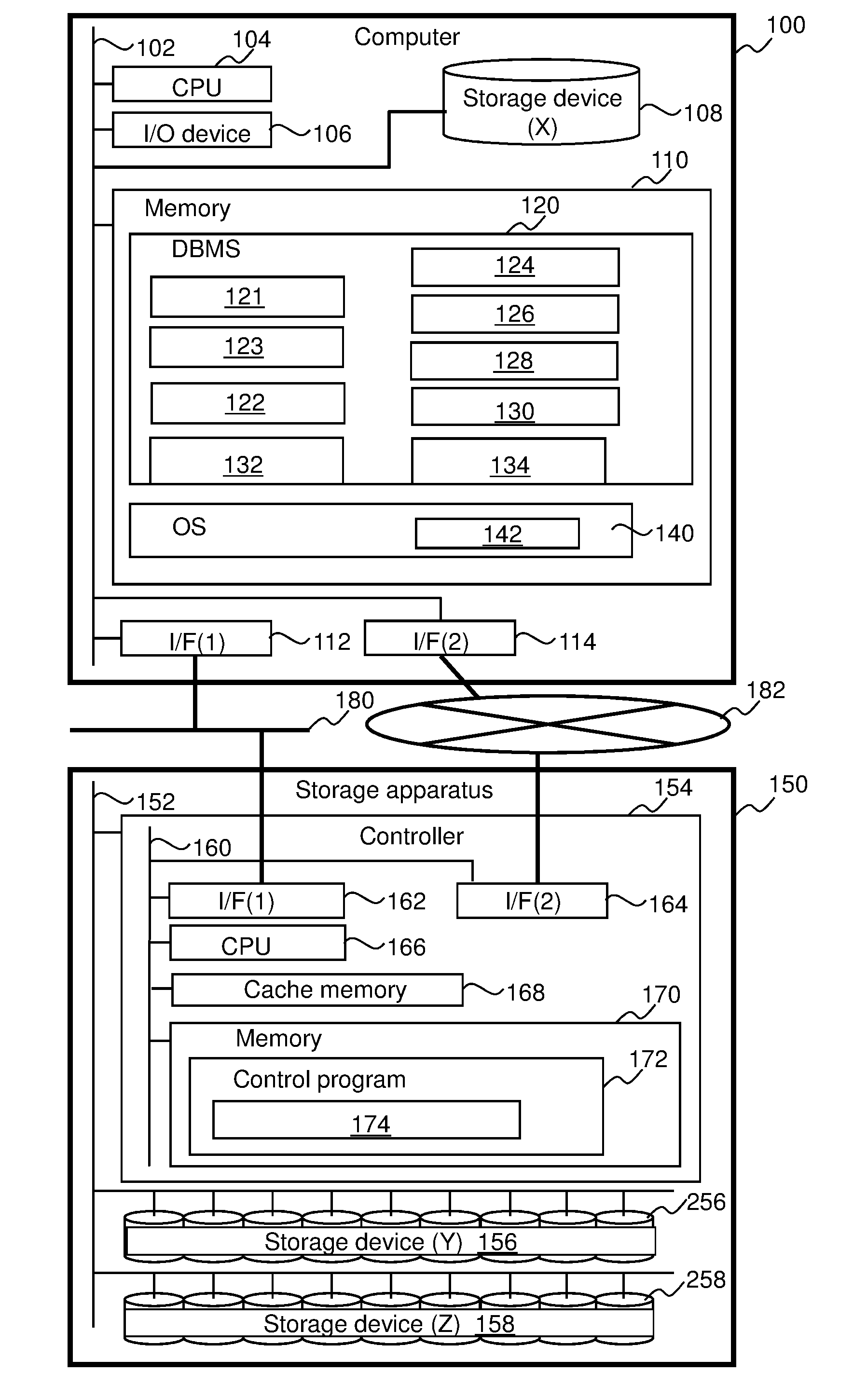
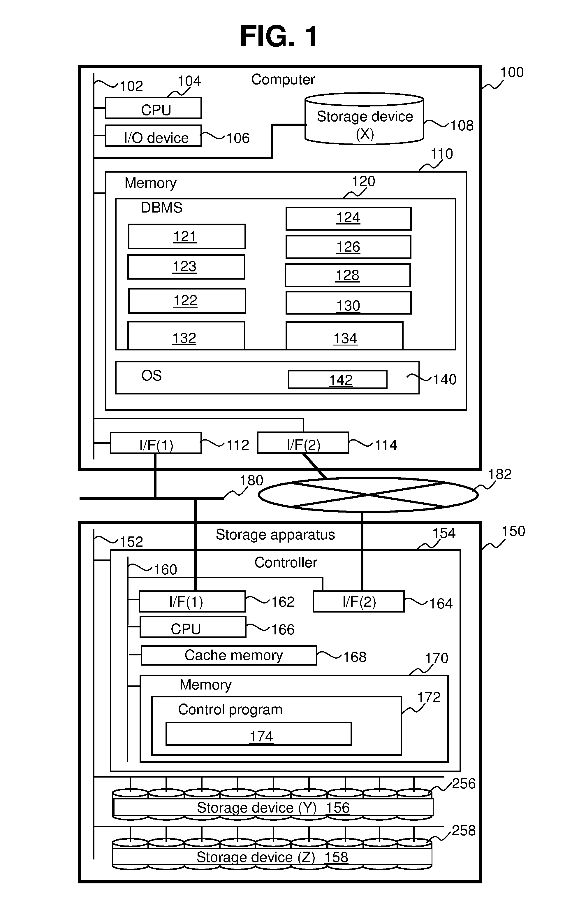
[0033]FIG. 11 is a diagram illustrating the outline of Embodiment 1.
[0034]A storage apparatus 150 is coupled to a computer 100 via a communication network 182. The computer 100 includes a storage device (X) 108 and executes an operating system (hereinafter, an OS) 140 and a DBMS 120. The storage apparatus 150 includes a controller 154 and provides a storage device (Y) 156 and a storage device (Z) 158 to the computer 100. The storage device (X) 108, the storage device (Y) 156, and the storage device (Z) 158 stores the data of a database (hereinafter, a DB).
[0035]The DBMS 120 includes a query execution part 122, an I / O processing part (A) 132, and an I / O processing part (B) 134.
[0036]The query execution part 122 can execute at least two tasks in parallel. For example, the query execution part 122 dynamically generates tasks for executing a database operation (hereinafter, a DB operation) and executes the tasks generated dynamically. When two or more executable tasks are present, the q...
embodiment 2
[0097]Embodiment 2 will be described below. Difference features from Embodiment 1 will be described mainly, and the description of the same features as those of Embodiment 1 will not be provided or may be simplified.
[0098]In Embodiment 2, after it is determined whether an average of I / O response time of an I / O destination storage device is shorter than an I / O method selection threshold, auxiliary determination on whether an I / O method corresponding to the determination result can be selected is performed.
[0099]FIG. 12 illustrates a portion of the flowchart of execution of tasks according to Embodiment 2.
[0100]When an average of I / O response time of an I / O destination storage device is shorter than an I / O method selection threshold (step 706: Yes), the query execution part 122 performs first auxiliary determination on whether it is okay to select the synchronous I / O method (step 1201). When the average of I / O response time of the I / O destination storage device is equal to or larger t...
embodiment 3
[0109]Embodiment 3 will be described below. Difference features from Embodiments 1 and 2 will be described mainly, and the description of the same features as those of Embodiments 1 and 2 will not be provided or may be simplified.
[0110]FIG. 13 is a diagram illustrating a configuration example of a computer system according to Embodiment 3.
[0111]A plurality of storage apparatuses 150A and 150B, respectively, having a plurality of storage devices (Y) 156 and (Z) 158 having different I / O response speeds are provided. The computer 100 is coupled to the plurality of storage apparatuses 150A and 150B.
[0112]In Embodiment 3, the synchronous I / O method (the I / O processing part (A)) 132 is selected when an I / O destination is the storage device (Y) 156, and the asynchronous I / O method (the I / O processing part (B)) 134 is selected when the I / O destination is the storage device (Z) 158.
PUM
 Abstract
Description
Claims
Application Information