In situ overvoltage protection for active bridge applications

Active Publication Date: 2017-01-05
STMICROELECTRONICS INT NV
View PDF2 Cites 4 Cited by
  • Summary
  • Abstract
  • Description
  • Claims
  • Application Information

AI Technical Summary

Benefits of technology

[0008]One embodiment is a bridge circuit including in situ overvoltage protection for switches of a power stage of the bridge circuit. A voltage source provides a supply voltage to the power stage and to a high speed overvoltage detector. The overvoltage detector detects whether there is an overvoltage condition in the supply voltage by comparing the supply voltage to a threshold voltage. If the supply voltage is higher than the threshold voltage, the overvoltage detector outputs an overvoltage signal that disables the switches of the half bridge circuit before the switches can be damaged by the overvoltage situation. In one embodiment, the power stage includes a half bridge. The half bridge includes two switches connected in series. When the overvoltage detector outputs the overvoltage signal, both switches in the half bridge are disabled. With both switches of

Problems solved by technology

This can lead to reduced size and cos

Method used


Image

  • In situ overvoltage protection for active bridge applications
  • In situ overvoltage protection for active bridge applications
  • In situ overvoltage protection for active bridge applications

Examples


Embodiment Construction

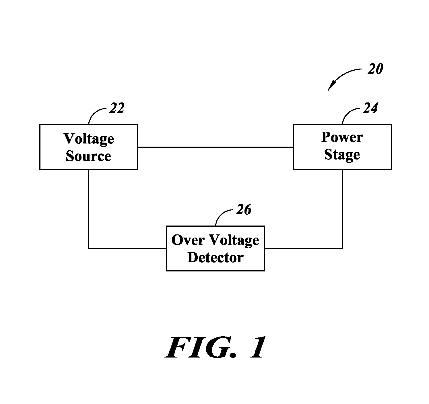
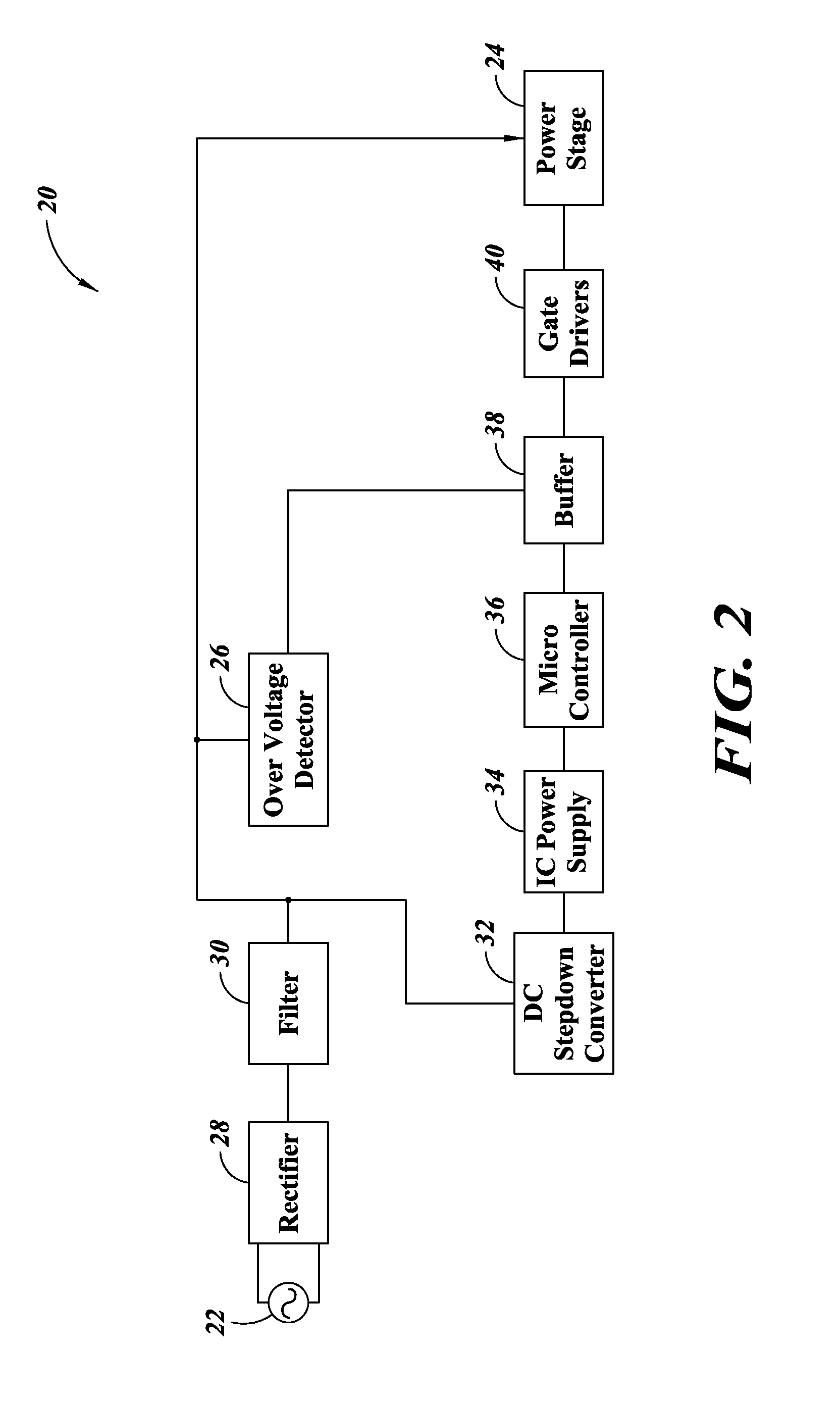
[0016]FIG. 1 is a block diagram of a bridge circuit 20, according to one embodiment. The motor control circuit includes a voltage source 22 and a power stage 24 coupled to the voltage source 22. The bridge circuit 20 further includes an overvoltage detector 26 coupled to the voltage source 22 and the power stage 24.

[0017]The voltage source 22 outputs a supply voltage to the power stage 24. In one embodiment the supply voltage is a DC voltage. Alternatively, the supply voltage can be an AC voltage such as a two phase or three phase voltage.

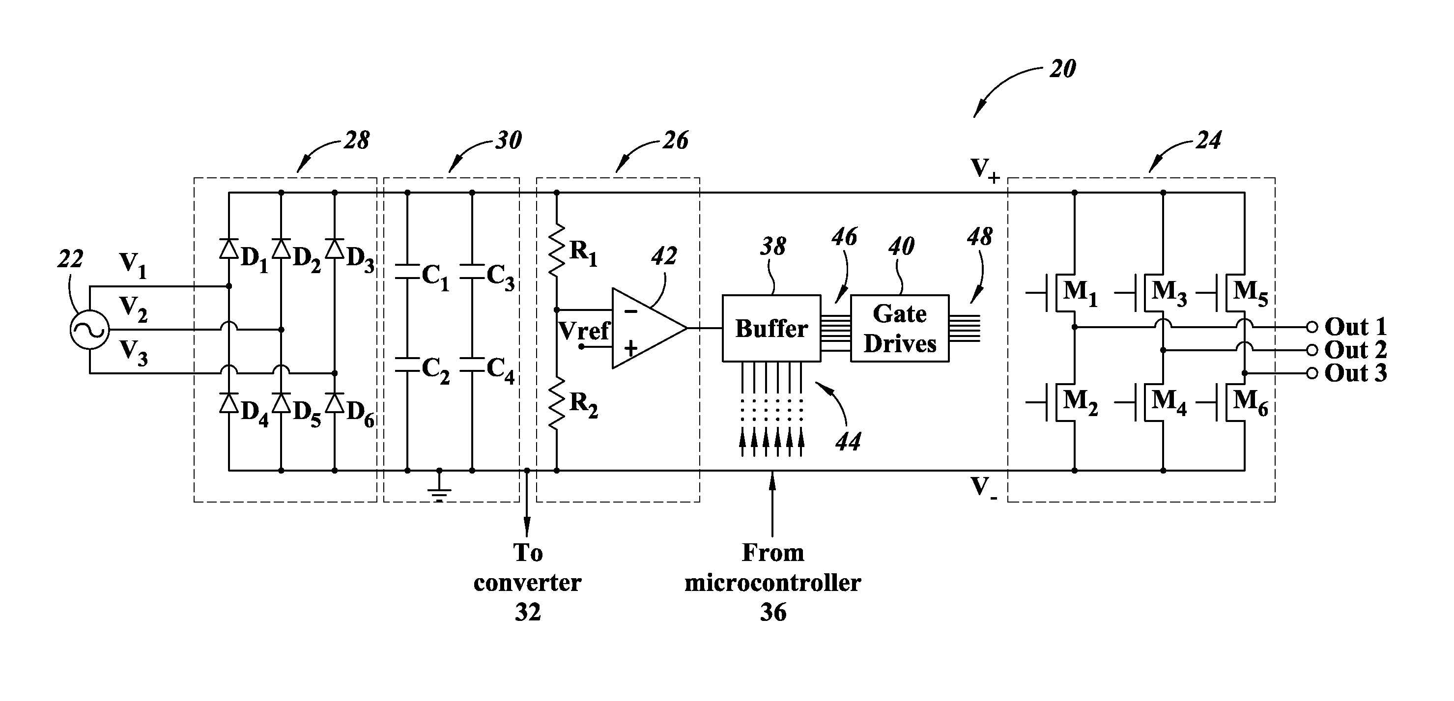
[0018]The power stage 24 receives the supply voltage and provides one or more output voltages. In one embodiment, the bridge circuit includes one or more half bridge circuits each including a pair of switches connected in series. The output voltages of the bridge circuit can include voltages present at the midpoint of each half bridge. The output voltages can be supplied to a load, such as a motor. In this way, the power stage 24 can drive the moto...


PUM


Abstract

An overvoltage protection device protects a half bridge circuit that receives a supply voltage. The overvoltage protection device includes a high speed overvoltage detector that receives the supply voltage, detects whether an overvoltage situation is present, and outputs an overvoltage signal that disables the switches of the half bridge circuit before the switches can be damaged by the overvoltage situation. With both the switches of the half-bridge disabled, the entire supply voltage appears across the two switches in series, by which each switch only receives half the entire voltage. Thus, by quickly disabling both switches of the half-bridge each switch only needs a maximum voltage rating equal to half the maximum voltage rating of the half bridge circuit as a whole. This leads to reduced size and cost for the switches of the half-bridge circuit.

Description

BACKGROUND[0001]Technical Field[0002]The present disclosure relates to the field of overvoltage protection and, more particularly, to in situ overvoltage protection for active bridge applications.[0003]Description of the Related Art[0004]Active switches such as MOS transistors, bipolar transistors, and IGBTs are used in bridge circuits for controlled rectification and inverter stages.[0005]One common type of bridge circuit is the H-bridge. The H-bridge is formed by connecting two half bridges in parallel. Typically, each half bridge includes two active switches in series. A 3-phase bridge, typically used in brushless DC motor control, is formed by connecting three half bridges in parallel.[0006]In applications where AC mains are rectified and filtered to generate a DC bus voltage supply for powering the active bridge inverter, overvoltage protection schemes are typically employed to protect the bridge circuit and the load from overvoltage conditions on the AC main.[0007]Existing met...

Claims


Application Information

Patent Timeline
IPC IPC(8): H02M1/32H02P7/00H02M7/06
CPCH02M1/32H02H7/1222H02M5/458H02P29/0241
Inventor SONA, SAURABH
Owner STMICROELECTRONICS INT NV
Why Eureka
Try Eureka