Low-frequency transformer with built-in shielding layer

A shielding layer and transformer technology, which is applied in the field of low-frequency transformers, can solve the problems of poor insulation performance and poor convenience of pin disassembly and assembly, and achieve the effects of improving shock resistance, improving heat dissipation performance, and increasing heat dissipation area

Inactive Publication Date: 2020-02-21
怀化市中三源电子有限公司
View PDF0 Cites 0 Cited by
  • Summary
  • Abstract
  • Description
  • Claims
  • Application Information

AI Technical Summary

Problems solved by technology

[0004] The purpose of the present invention is to propose a low-frequency transformer with a built-in shielding layer in order to solve the problems of poor insulation performance and poor convenience of pin disassembly and assembly.

Method used


Image

  • Low-frequency transformer with built-in shielding layer
  • Low-frequency transformer with built-in shielding layer
  • Low-frequency transformer with built-in shielding layer

Examples


Embodiment 1

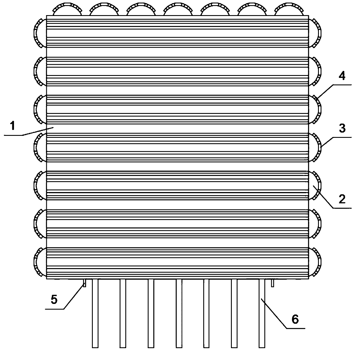
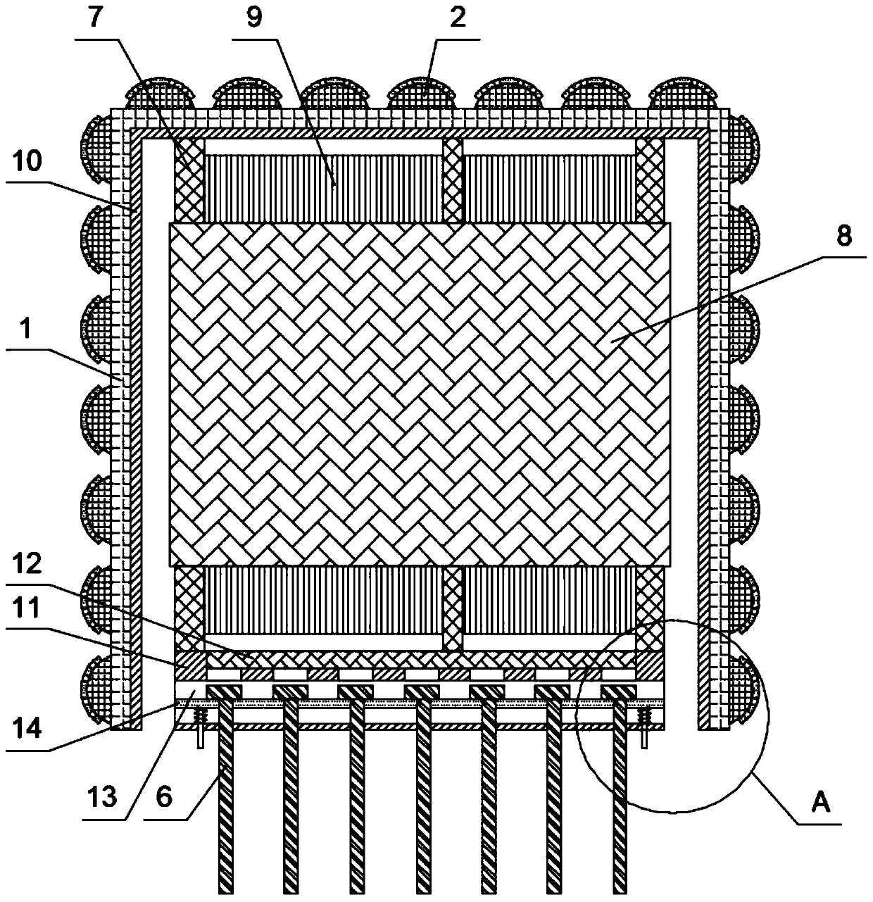
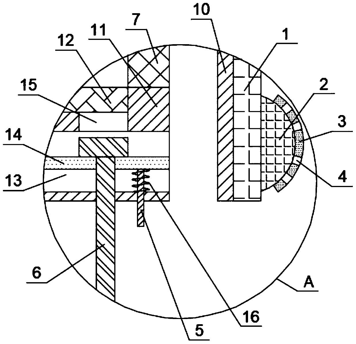
[0034] Example 1, please refer to Figure 1-5 , the present invention provides a technical solution: a low-frequency transformer with a built-in shielding layer, including a shell 1 with a bottom opening structure, a skeleton 7, a coil 9, pins 6 and an iron core 8, and the inner side of the shell 1 is fixedly connected with a shielding layer 10, The inner side of the shielding layer 10 is fixedly connected with a skeleton 7, and the inner side of the skeleton 7 is fixedly connected with an iron core 8, the outer surface of the iron core 8 is provided with a coil 9, and the bottom of the skeleton 7 is fixedly connected with two sets of mounting brackets with concave tops. plate 11, the inside of the top of the mounting plate 11 is fixedly connected with a conductive sheet 12, the inside of the mounting plate 11 is provided with a chute 13, and the inside of the mounting plate 11 is located above the chute 13 to provide a plurality of sets of limiting grooves 15, chute 13 There ...

Embodiment 2

[0035] Embodiment two, such as image 3 and Figure 5 As shown, the outer end surface of the housing 1 is fixedly connected with multiple sets of heat dissipation convex fins 2 with a hemispherical cross-section. The groove 4 and the setting of the heat dissipation groove 4 reduce the resistance of the flexible pad 3 to the heat dissipation of the heat dissipation convex fin 2. The flexible pad 3 is made of organic silicon material. The anti-shock performance improves the anti-seismic performance of low-frequency transformers. At the same time, organic silicon products have good electrical insulation properties, and have certain voltage resistance, arc resistance and corona resistance performance, so that low-frequency transformers have certain anti-arc capabilities. .

Embodiment 3

[0036] Embodiment three, such as figure 2 As shown, the shell 1 and the heat dissipation fins 2 are made of aluminum nitride ceramics, the bottom of the mounting plate 11 is flush with the bottom of the shell 1 in the horizontal direction, and the contact area with the outside air is increased through the heat dissipation fins 2, improving the The heat dissipation effect of the low-frequency transformer is improved, and the heat dissipation convex fin 2 and the shell 1 are made of aluminum nitride ceramic material, and the heat generated by the low-frequency transformer is discharged outward by using the good thermal conductivity of the aluminum nitride ceramic material, thereby improving the performance of the transformer. For the heat dissipation performance of the low-frequency transformer, the bottom of the mounting plate 11 is flush with the bottom of the housing 1 in the horizontal direction, ensuring that the bottom of the housing 1 can be attached to the top of the PBC...


PUM


Abstract

The invention discloses a low-frequency transformer with a built-in shielding layer. The low-frequency transformer comprises a shell with a bottom opening structure, a framework, a coil, pins and an iron core, the inner side of the shell is fixedly connected with a shielding layer, the inner side of the shielding layer is fixedly connected with a framework, the inner side of the framework is fixedly connected with the iron core, the outer surface of the iron core is provided with the coil, the bottom of the framework is fixedly connected with two groups of mounting plates of which the tops areof concave structures, and the inner sides of the tops of the mounting plates are fixedly connected with conducting strips. In the present invention, firstly, the shielding layer is arranged on the inner side of a shell, the shell is made of an aluminum nitride ceramic material, by means of the good insulating property and heat conductivity of the aluminum nitride ceramic material, the insulatingproperty of the low-frequency transformer is improved while the low-frequency transformer is subjected to good electromagnetic shielding, then, the pins are inlaid into the limiting grooves to be fixed under the extrusion effect of extrusion springs, installation of the pins is completed, and therefore, convenient disassembly and assembly of the pins are achieved.

Description

technical field [0001] The invention relates to the technical field of low-frequency transformers, in particular to a low-frequency transformer with a built-in shielding layer. Background technique [0002] Low-frequency transformers are used to propagate signal voltage and signal power, and can also achieve impedance matching between circuits, and have an isolation effect on direct current. There is no difference in principle between high-frequency transformers and low-frequency transformers. However, due to the different frequencies of high frequency and low frequency, the iron cores used in transformers are different. Low-frequency transformers generally use silicon steel sheets with high magnetic permeability, while high-frequency transformers use high-frequency ferrite cores. [0003] Most low-frequency transformers use the shielding layer of the shell structure. Setting the shell as a metal shielding material or applying a shielding coating will affect the performanc...

Claims


Application Information

Patent Timeline
Patent Type & Authority Applications(China)
IPC IPC(8): H01F27/00H01F27/02H01F27/06H01F27/22H01F27/29H01F27/36
CPCH01F27/00H01F27/02H01F27/025H01F27/06H01F27/22H01F27/29H01F27/36
Inventor 李永青
Owner 怀化市中三源电子有限公司
Why Eureka
Try Eureka