Optical sensor with narrow angular response

a technology of optical sensors and angular response, applied in the field of optical sensors, can solve the problems of narrow interference with the light from the target volume of users' bodies, and particular reducing, and achieve the effect of limiting the angular response of optical sensors

Inactive Publication Date: 2017-01-12
LFOUNDRY S R I
View PDF2 Cites 1 Cited by
  • Summary
  • Abstract
  • Description
  • Claims
  • Application Information

AI Technical Summary

Benefits of technology

[0010]Moreover, a specific object of the present invention is that of providing an optical sensor with narrow angular response such that to minimize side light interference.
[0022]More and more conveniently, each photodetector active area has a size, wherein the sizes of the photodetector active areas and the relative position of said photodetector active areas with respect to the apertures formed through the light shielding means further limit the angular response of the optical sensor.

Problems solved by technology

In fact, due to the non-perfect contact between the optical sensors and the user's skin, a gap is interposed therebetween, which allows side light to reach the detectors, thereby interfering with the light from the target volume of the user's body and thus affecting, in particular reducing, Signal-to-Noise Ratio (SNR).

Method used


Image

  • Optical sensor with narrow angular response
  • Optical sensor with narrow angular response
  • Optical sensor with narrow angular response

Examples


Embodiment Construction

[0032]The following discussion is presented to enable a person skilled in the art to make and use the invention. Various modifications to the embodiments will be readily apparent to those skilled in the art, without departing from the scope of the present invention as claimed. Thus, the present invention is not intended to be limited to the embodiments shown and described, but is to be accorded the widest scope consistent with the principles and features disclosed herein and defined in the appended claims.

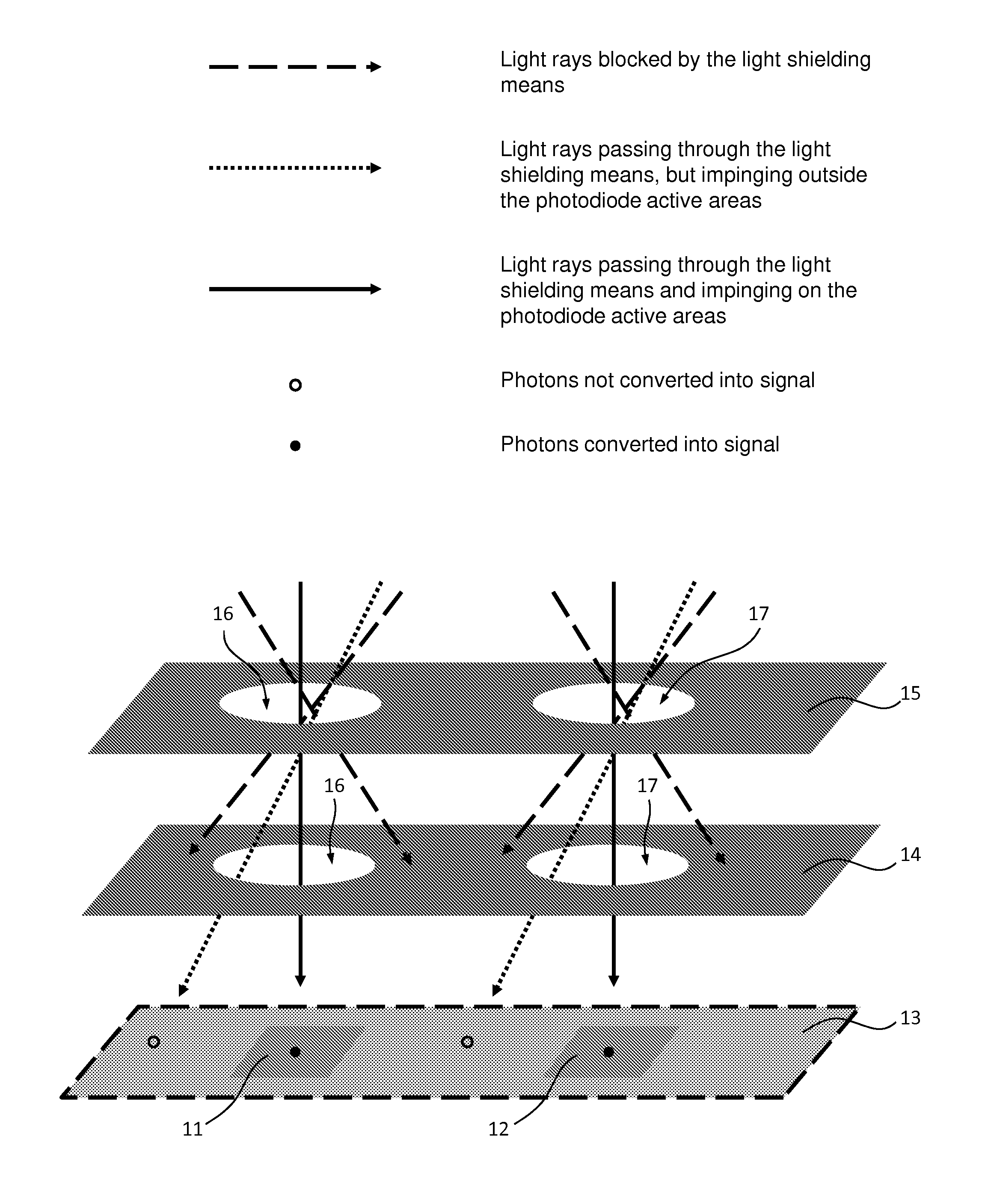
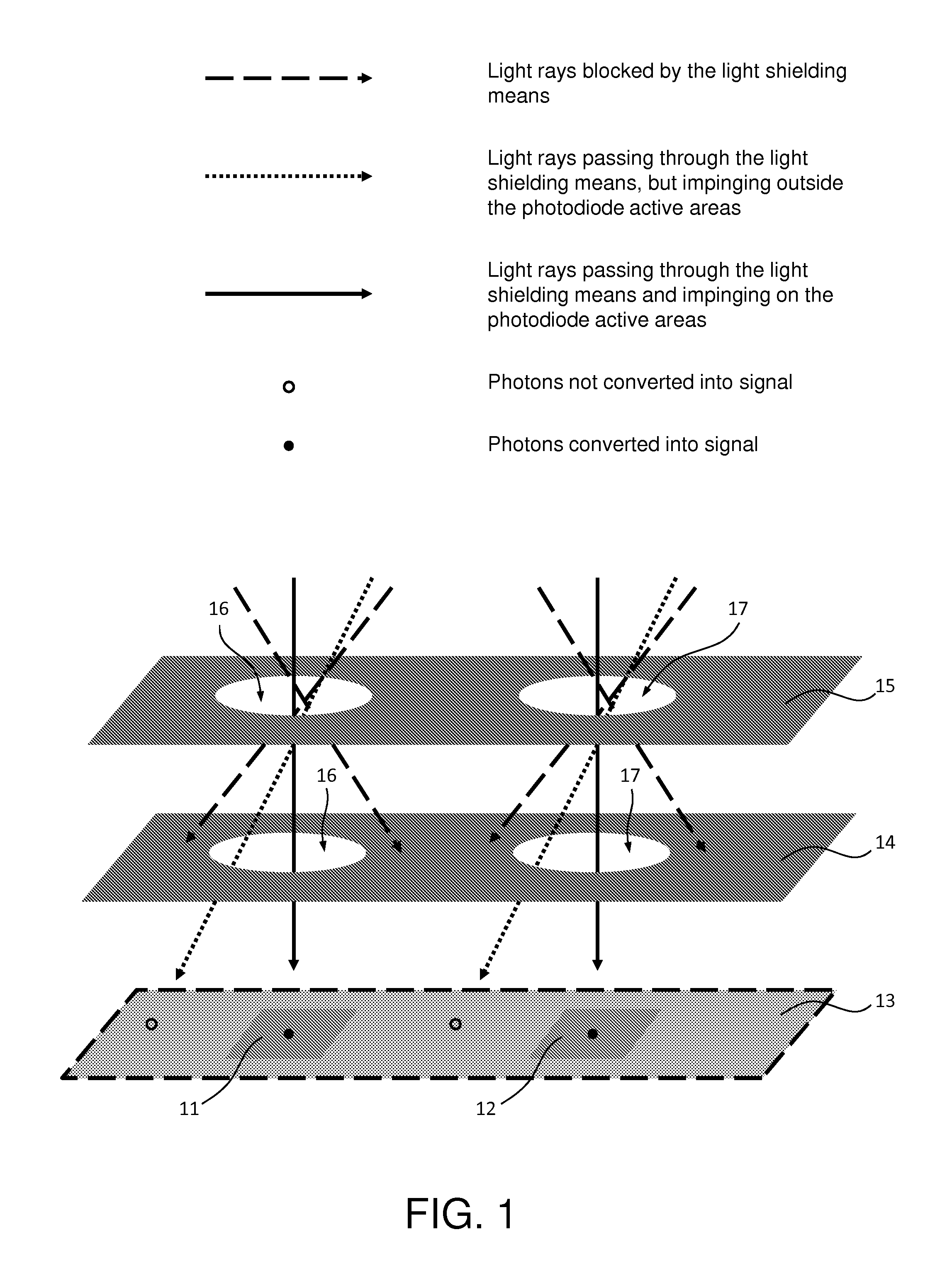
[0033]The present invention stems from Applicant's idea of integrating, into an optical sensor based on CMOS technology, light shielding means designed to define an angular range around a given incident direction and to suppress incident light with incidence angle outside the defined angular range. Preferably, said optical sensor equipped with the light shielding means can be integrated into a System-on-a-chip (SoC) along with read-out circuitry, Analogue Signal Processor (ASP), Di...


PUM


Abstract

The present invention relates to an optical sensor that is formed in an integrated circuit based on CMOS technology and that comprises: one or more photocells including one or more photodetector active areas and an optical stack formed on the photodetector active area(s); and light shielding means, that are formed in or on the optical stack, and are configured, for each photocell, to define an angular range around a given incident direction with respect to said photocell, block incident light with incidence angle outside the defined angular range, and allow incident light with incidence angle within the defined angular range to propagate through the optical stack down to a respective photodetector active area; whereby the light shielding means limit angular response of the optical sensor.

Description

CROSS-REFERENCE TO RELATED APPLICATIONS[0001]The present application claims priority under 35 U.S.C. §119 to Italian Patent Application No. 102015000031525, filed Jul. 7, 2015, the entirety of which is incorporated herein by reference.FIELD OF THE INVENTION[0002]The present invention relates to the sector of optical sensors and, specifically, to an optical sensor with narrow angular response. In particular, the present invention finds advantageous, but non-limitative, application in measuring devices, such as wearable biometric monitoring devices.BACKGROUND OF THE INVENTION[0003]Recent advances in miniaturization and detection accuracy of optical sensors have allowed the use of such devices in many fields.[0004]For example, optical sensors are currently used in wearable devices to monitor, in a non-invasive fashion, biometric parameters, such as heart rate and blood oxygenation. In particular, these wearable devices, such as watches, arm bands and headsets, can include:[0005]a light...

Claims


Application Information

Patent Timeline
Patent Type & Authority Applications(United States)
IPC IPC(8): A61B5/00H01L27/146
CPCA61B5/0059H01L27/14643A61B2562/185A61B5/6801A61B2562/0238H01L27/14603H01L27/14623H01L27/14625
Inventor SPAZIANI, FABIODEL MONTE, ANDREAMARGUTTI, GIOVANNIDE AMICIS, GIOVANNI
Owner LFOUNDRY S R I
Why Eureka
Try Eureka