Al technical title is built by PatSnap Al team. It summarizes the technical point description of the patent document.
a dielectric material and flow control technology, applied in the field of fluid dynamics, can solve the problems of difficult to measure small changes in drag with high accuracy, energy consumed to deal with turbulent boundary layer flows, etc., and achieve the effect of optimizing the delaying of turbulent flow
Active Publication Date: 2017-01-12
CALIFORNIA INST OF TECH
View PDF9 Cites 5 Cited by
Summary
Abstract
Description
Claims
Application Information
AI Technical Summary
This helps you quickly interpret patents by identifying the three key elements:
Problems solved by technology
Method used
Benefits of technology
[0011]The various embodiments according to the present disclosure relate to methods and devices for full active control on compliance and rugosity of surfaces using dielectric materials and in some cases using dielectric elastomers. According to some embodiments of the present disclosure, by using a compliant electrically responsive polymer in a multilayered active surface of a vehicle subjected to a fluid, such active control can allow control of the boundary layer transition, such as, for example, optimizing the delaying of turbulent flow on the vehicle. An exemplary multilayered active surface according to some embodiments of the present disclosure can be developed by combining a stiff layer with a compliant electrically responsive polymer such as a ferroelectric polymer or a dielectric elastomer.
Problems solved by technology
A critical issue in the aeronautics industry is the energy consumed to deal with turbulent boundary layer flows.
However, it is known in the art that it is difficult to measure small changes in drag with high accuracy.
Method used
Image
Click on the blue label to locate the original text in one second.
Reading with bidirectional positioning of images and text.
Examples
Embodiment Construction
[0025]Throughout this description, embodiments and variations are described for the purpose of illustrating uses and implementations of the inventive concept. The illustrative description should be understood as presenting examples of the inventive concept, rather than as limiting the scope of the concept as disclosed herein.
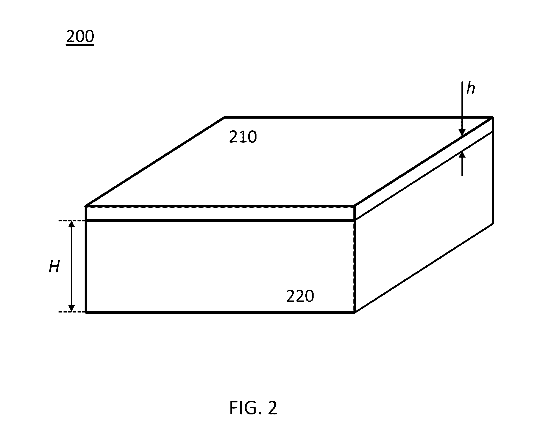
[0026]As known to a person skilled in the art, turbulent drag can be reduced to some extent by using compliant coatings on rigid walls, where the compliant coatings are slightly deformed by boundary layer flows. Corresponding deformations vary as the flow changes along the coated surface in a temporal or spatial manner. Usage of compliant coatings can result in a passive technique to adapt the shape of the surface in contact with the flow.
[0027]The consequences of using such passive technique on the turbulent drag are significant, as illustrated, for example, in an experiment realized by Choi et al. (reference [3]), where a corresponding set up consisted in plac...
PUM
Abstract
A multilayered active surface is presented whose rugosity can be controlled by an applied electrical field. Varying the applied electrical field can control the rugosity of the surface which makes contact with a fluid, and thereby can affect instabilities of the boundary layer. A middle layer of the multilayered active surface can be made of a compliant electroactive material. In some cases, a pre-stretch in the middle layer can predefine a rugosity of the multilayered active surface without an applied electrical field, in which case an applied electrical field can further alter the rugosity in both amplitude and spatial periodicity and ultimately result to a smooth surface for a higher value of the applied electrical field. A top layer and a bottom layer are constructed using conductive material and uses as electrodes coupled to a voltage source to generate the electric field that controls the rugosity of the surface.
Description
CROSS REFERENCE TO RELATED APPLICATIONS[0001]The present application claims priority to U.S. provisional Patent Application Ser. No. 62 / 188,927, filed on Jul. 6, 2015, for “Flow Control Technique by Dielectric Materials”, which is herein incorporated by reference in its entirety.[0002]The present application may be related to U.S. Pat. No. 8,276,851, entitled “Control of Aerodynamic Forces by Variable Wetted Surface Morphology”, issued Oct. 2, 2012, the disclosure of which is incorporated herein by reference in its entirety. The present application may further be related to U.S. Pat. No. 8,424,809, entitled “Control of Aerodynamic Forces by Variable Wetted Surface Morphology”, issued Apr. 23, 2013, the disclosure of which is incorporated herein by reference in its entirety. The present application may further be related to U.S. Pat. No. 9,315,259, entitled “Morphing Surfaces for the Control of Boundary Layer Transition”, issued Apr. 19, 2016, the disclosure of which is incorporated ...
Claims
Application Information
Patent Timeline
Application Date:The date an application was filed.
Publication Date:The date a patent or application was officially published.
First Publication Date:The earliest publication date of a patent with the same application number.
Issue Date:Publication date of the patent grant document.
PCT Entry Date:The Entry date of PCT National Phase.
Estimated Expiry Date:The statutory expiry date of a patent right according to the Patent Law, and it is the longest term of protection that the patent right can achieve without the termination of the patent right due to other reasons(Term extension factor has been taken into account ).
Invalid Date:Actual expiry date is based on effective date or publication date of legal transaction data of invalid patent.
Patent Type & Authority Applications(United States)