Projection apparatus

a projection device and projection technology, applied in the field of projection devices, can solve the problems of high manufacturing cost, difficult to reduce the size of the projection device, and ghosting

Active Publication Date: 2017-01-12
CITIZEN WATCH CO LTD
View PDF2 Cites 82 Cited by
  • Summary
  • Abstract
  • Description
  • Claims
  • Application Information

AI Technical Summary

Benefits of technology

[0024]According to the above projection apparatus, the apparatus is made smaller and the definition of the projected image is higher than would be the case if the configuration of the present invention were not employed.

Problems solved by technology

In this case, however, it is difficult to reduce the size of the apparatus and also the manufacturing cost is high.
Therefore, the emitted light also enters microlenses of adjacent pixels in the microlens array, thereby causing crosstalk, and in this case, the ghosting occurs in the displayed image.

Method used


Image

  • Projection apparatus
  • Projection apparatus
  • Projection apparatus

Examples


Embodiment Construction

[0043]Hereinafter, with reference to the accompanying drawings, a projection apparatus will be explained in detail. However, it should be noted that the present invention is not limited to the drawings or the embodiments described below.

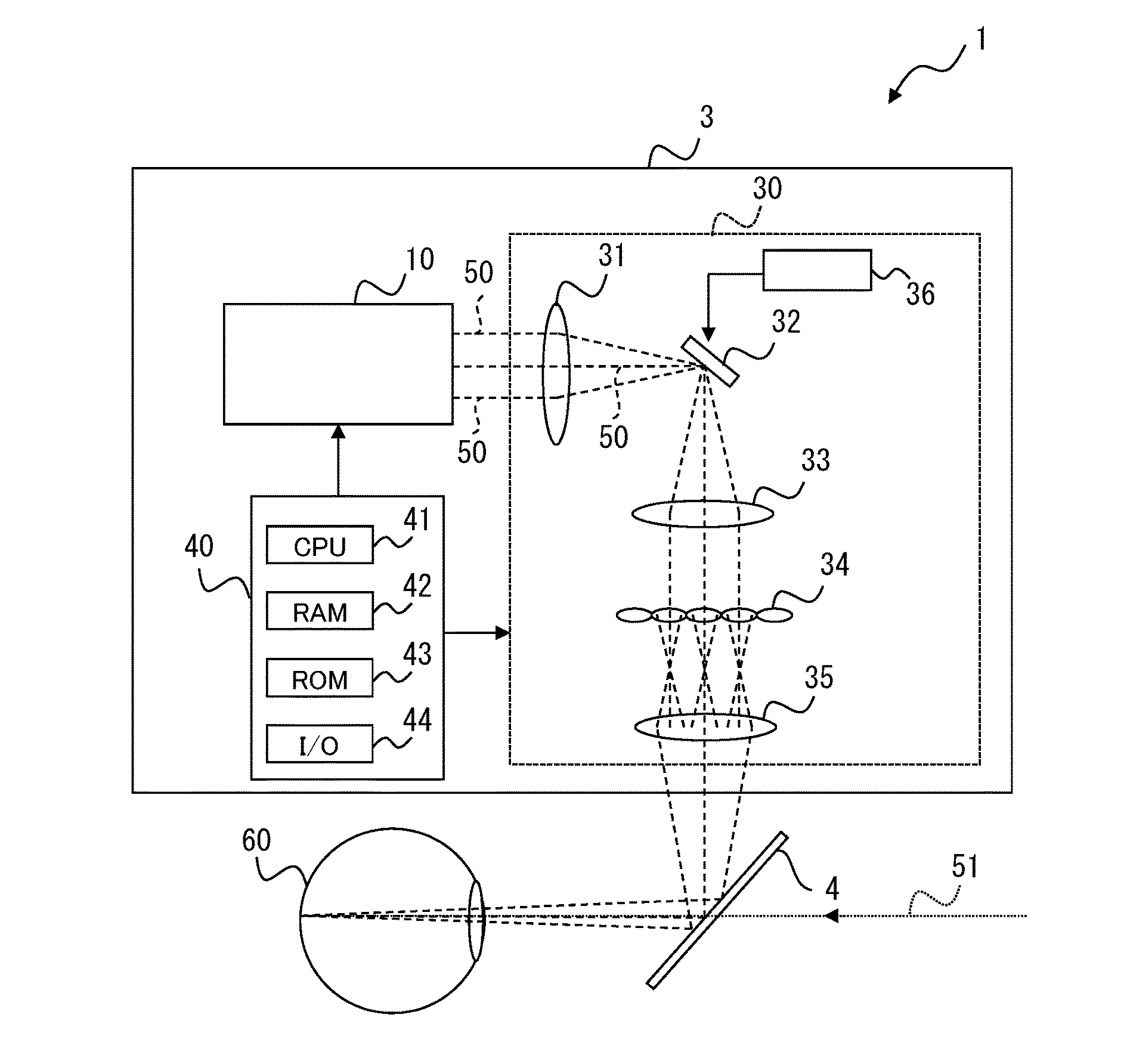
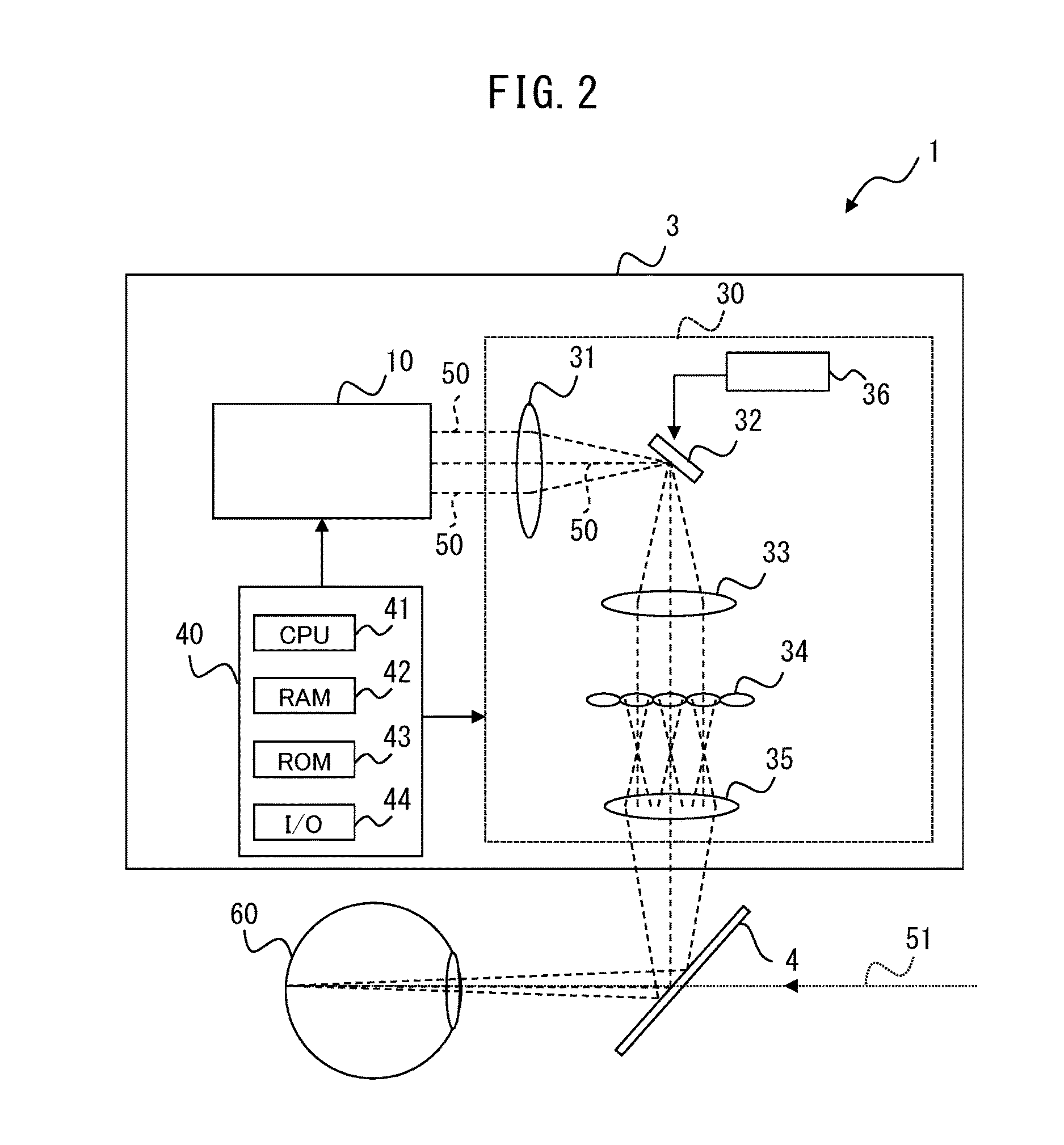
[0044]This projection apparatus emits a plurality of sets of laser beams, each set including at least a red laser beam, a green laser beam, and a blue laser beam, from emission ends of a plurality of fibers. The projection apparatus scans the laser beams two-dimensionally and changes the angle of the scanning light with microlenses. Thus, the projection apparatus creates the state of emitting multiple light rays whose positions and directions are controlled from each point on a virtual display plane, and projects the light rays on the retina of a user to project an image that allows the user to stereoscopically percept the image in accordance with the refocusing characteristic of the eyes.

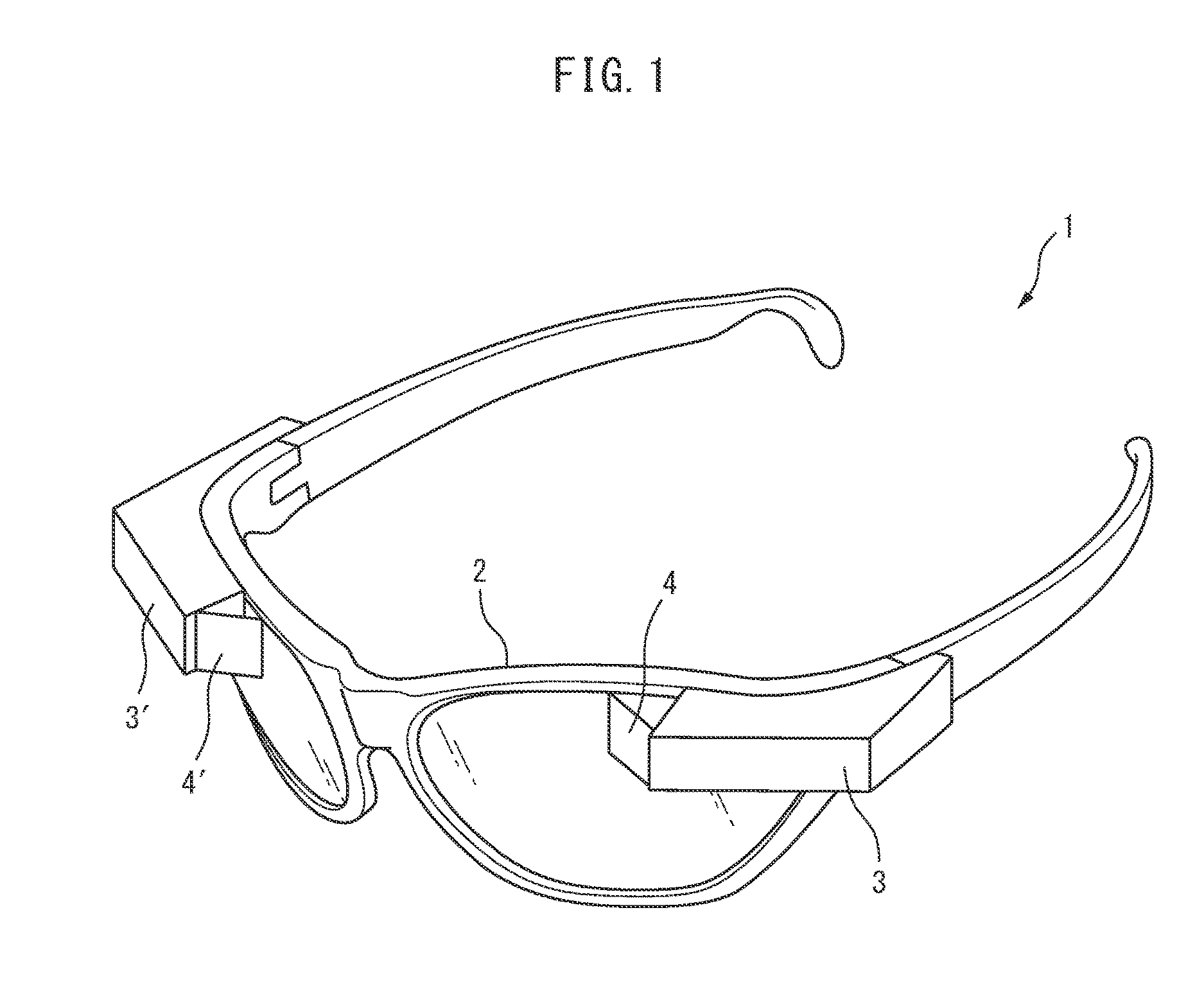
[0045]This projection apparatus can be used for, for example, ...


PUM


Abstract

Provided is a projection apparatus for projecting an image which can be seen stereoscopically, wherein the apparatus is made smaller and the definition of the projected image is higher than would be the case if the present configuration were not employed. The projection apparatus is an apparatus for projecting an image which can be seen stereoscopically, by scanning with one set of at least red, green, and blue laser beams, and includes a light source section that emits the laser beams, a scan section that scans a projection region two-dimensionally with the laser beams, and a microlens array that includes microlenses on which the laser beams from the scan section are incident and that changes emission angles of the laser beams in accordance with incident positions of the laser beams on the microlenses to create a light ray field in which light rays whose positions and directions are controlled are emitted from each point on surfaces of the microlenses in accordance with an image to be projected.

Description

TECHNICAL FIELD[0001]The present invention relates to a projection apparatus for projecting an image which can be seen stereoscopically, by laser beam scanning.BACKGROUND ART[0002]Some known apparatuses display an image using a plurality of micromirrors. For example, the image display apparatus according to Patent Literature 1 displays an image representing depth by reflecting light from a light source on a plurality of micromirrors to transmit selectively the resulting partial light through a plurality of lenses with different focal lengths.[0003]In addition, an image pickup apparatus (light field camera) capable of acquiring not only the light intensity distribution but also the information on the light incident direction has been known (for example, see Patent Literatures 2 and 3). The light field camera includes a microlens array between an image pickup lens and an image pickup element, and each microlens corresponds to a plurality of pixels of the image pickup element, thereby ...

Claims


Application Information

Patent Timeline
Patent Type & Authority Applications(United States)
IPC IPC(8): G02B27/22G02B6/06G02B26/08H04N9/31H04N13/04
CPCG02B27/2214H04N9/3129G02B6/06H04N13/0404G02B26/0833H04N9/3161G02B26/101G02B2027/0178G02B27/0172G02B3/0056G02B2027/0134G02B2027/0187G02B27/0093H04N13/305G02B30/40G03B21/208G02B30/27
Inventor IDE, MASAFUMI
Owner CITIZEN WATCH CO LTD
Why Eureka
Try Eureka