
In-situ ring-resonator-modulator calibration

a ring-resonator modulator and in-situ technology, applied in non-linear optics, instruments, optics, etc., can solve the problems of reducing the performance of ring-resonator modulators, and implementing silicon-photonic links, etc., to achieve the effect of maximizing the performance metri

Active Publication Date: 2017-01-12
ORACLE INT CORP
View PDF4 Cites 18 Cited by
  • Summary
  • Abstract
  • Description
  • Claims
  • Application Information

AI Technical Summary

Benefits of technology

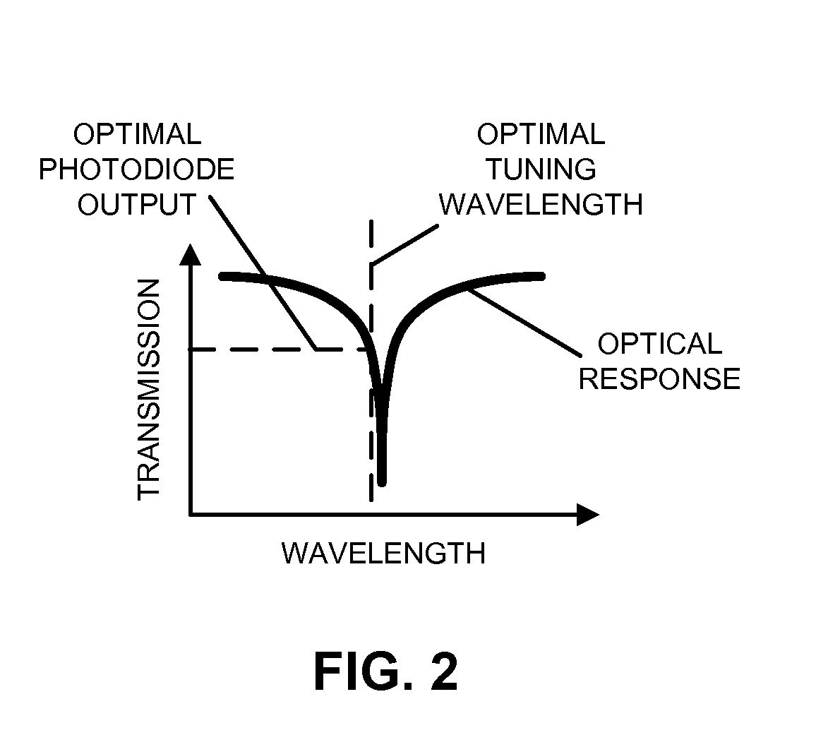
The control logic described in this patent adjusts the resonance wavelength to improve performance based on systematic under-relaxation, averaging of the performance metric, and progressively smaller changes when approaching the maximum. In simple terms, this means that the control logic optimizes the performance of the system by adjusting the resonance wavelength to make it more efficient.

Problems solved by technology

However, the performance of many of these components is dependent on temperature and / or wavelength changes, which remains an obstacle to implementing silicon-photonic links.
However, ring-resonator modulators typically work over a very small predefined range of wavelengths.
Consequently, variations in the carrier wavelengths of optical signals output from optical sources (such as lasers), as well as changes in the index of refraction of optical waveguides because of fabrication tolerances, temperature fluctuations and / or self-heating of the ring-resonator modulators, can degrade the performance of ring-resonator modulators.
In particular, a 1 C temperature change may cause a 110 pm shift in the resonance wavelength of the ring-resonator modulator, which can completely overpower voltage modulation of the ring-resonator modulator.

Method used


Image

  • In-situ ring-resonator-modulator calibration
  • In-situ ring-resonator-modulator calibration
  • In-situ ring-resonator-modulator calibration

Examples


Embodiment Construction

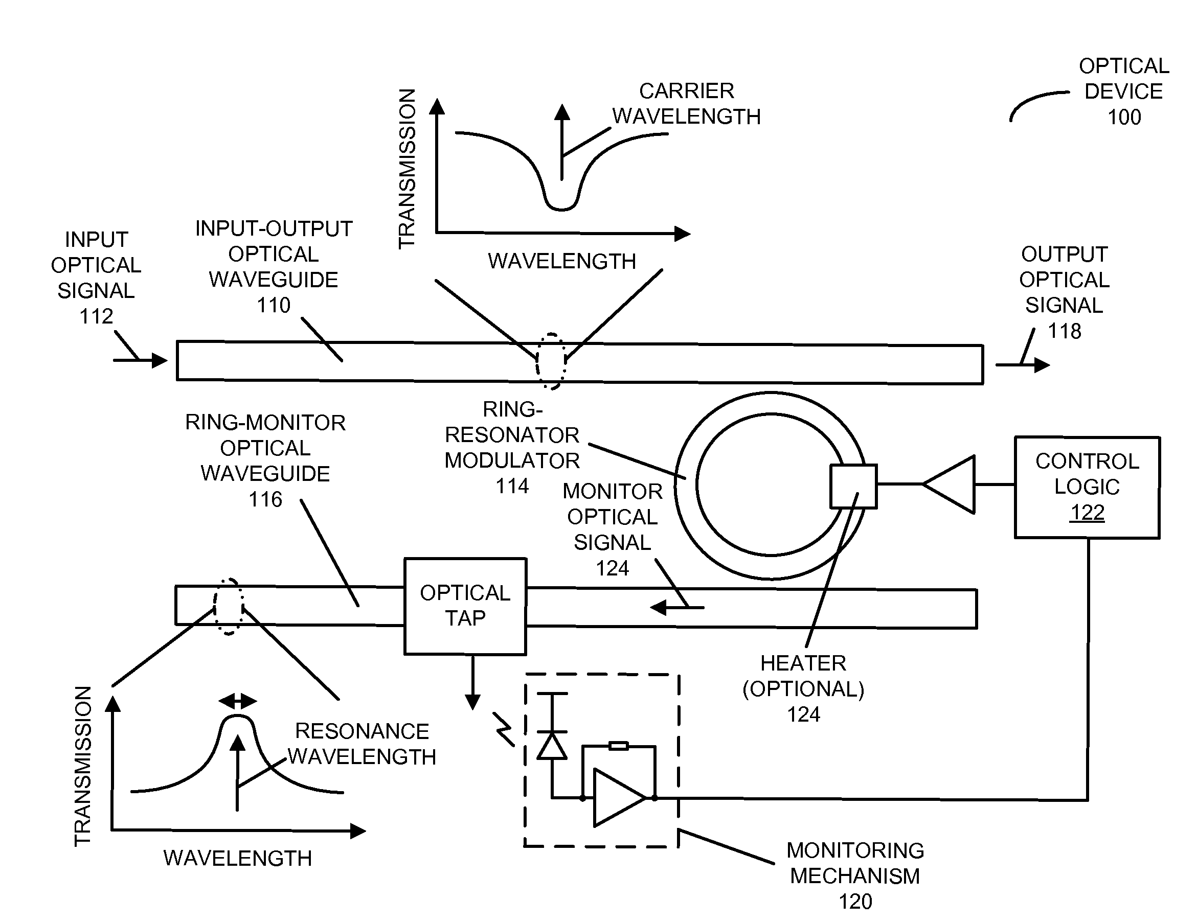
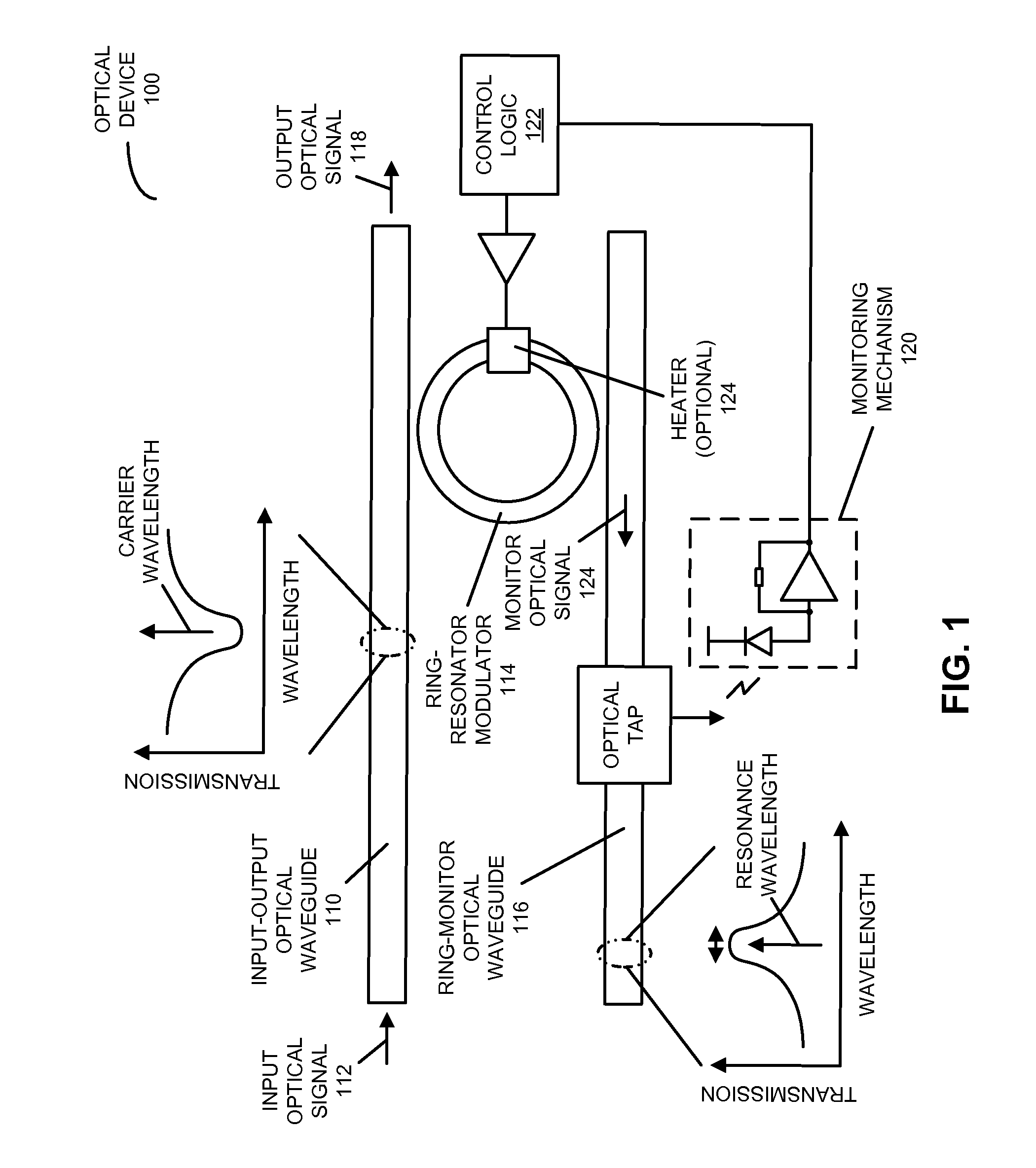
[0026]Embodiments of an optical device, a system that includes the optical device, and a technique for locking a resonance wavelength of a ring-resonator modulator to a carrier wavelength of an optical signal are described. In the optical device, a ring-resonator modulator, having an adjustable resonance (center) wavelength, receives the optical signal that includes the carrier wavelength from an input-output optical waveguide. Then, a monitoring mechanism monitors a performance metric (such as an average power or a signal swing) of a monitor optical signal from the ring-resonator modulator. Moreover, control logic in the optical device adjusts the resonance wavelength based on the monitored performance metric so that the performance metric is optimized (e.g., the resonance wavelength is locked to the carrier wavelength). In particular, the control logic may apply a change to an adjustment signal that is provided to the ring-resonator modulator. If the change increases the performan...


PUM


Abstract

In an optical device, a ring-resonator modulator, having an adjustable resonance (center) wavelength, receives an optical signal that includes a carrier wavelength from an input-output optical waveguide. Then, a monitoring mechanism monitors a performance metric (such as an average power or a signal swing) of a monitor optical signal from the ring-resonator modulator. Moreover, control logic in the optical device adjusts the resonance wavelength based on the monitored performance metric so that the resonance wavelength is locked to the carrier wavelength. In particular, the control logic may apply a change to an adjustment signal that is provided to the ring-resonator modulator. If the change increases the performance metric, the control logic may continue to modify the resonance wavelength. Otherwise, the control logic may modify the resonance wavelength by applying one or more changes, having an opposite sign to the change, to the adjustment signal.

Description

CROSS-REFERENCE TO RELATED APPLICATIONS[0001]This application claims priority under 35 U.S.C. §119 to U.S. Provisional Patent Application No. 61 / 913,560, entitled “In-Situ Calibration of an Optical Ring Modulator,” by Philip Amberg, Eric Chang, and Frankie Y. Liu, filed Dec. 9, 2013 (Attorney Docket No. ORA14-0497PSP), the contents of which are herein incorporated by reference.GOVERNMENT LICENSE RIGHTS[0002]This invention was made with United States government support under Agreement No. HR0011-08-9-0001 awarded by DARPA. The United States government has certain rights in the invention.BACKGROUND[0003]Field[0004]The present disclosure relates to techniques for communicating optical signals. More specifically, the present disclosure relates to wavelength-locking a ring-resonator modulator.[0005]Related Art[0006]Silicon photonics is a promising technology that can provide large communication bandwidth, low latency and low power consumption for inter-chip and intra-chip connections. In...

Claims


Application Information

Patent Timeline
IPC IPC(8): G02F1/01
CPCG02F1/0121G02F1/025G02F1/3132G02F2201/58G02F2203/15
Inventor AMBERG, PHILIPCHANG, ERIC Y.LIU, FRANKIE Y.
Owner ORACLE INT CORP
Learn More