Magnetic assembly and power suppy system with same

a technology of magnetic assembly and power suppy, which is applied in the direction of electric variable regulation, process and machine control, instruments, etc., can solve the problems of large magnetic loss, high manufacturing cost of power supply system, and increased volume and weight of overall power supply system, so as to reduce cost, increase power density, and reduce volume and weight of magnetic assembly

Active Publication Date: 2017-01-12
DELTA ELECTRONICS SHANGHAI CO LTD
View PDF10 Cites 18 Cited by
  • Summary
  • Abstract
  • Description
  • Claims
  • Application Information

AI Technical Summary

Benefits of technology

[0005]An object of the present invention provides a magnetic assembly and a power supply system with the magnetic assembly. The magnetic assembly integrates plural magnetic elements. Consequently, the volume and weight of the magnetic assembly have been reduced, and the power supply system has reduced cost and increased power density.

Problems solved by technology

Since the magnetic element occupies large fractions of volume and weight of the overall power supply system, it is an important issue to reduce the volume and weight of the magnetic element in order to increase the power density of the power supply system.
However, since the magnetic elements of the plural converters have individual magnetic cores and the magnetic flux paths are independent, the volume and weight of the overall power supply system are increased and the fabricating cost of the power supply system is high.
Moreover, during operations of the power supply system, the magnetic core of the magnetic element of each converter will result in a large magnetic loss.
Since the magnetic cores of the magnetic elements of the plural converters in the conventional power supply system are independent and the magnetic flux paths are independent, the conventional power supply system has large magnetic loss and volume.

Method used


Image

  • Magnetic assembly and power suppy system with same
  • Magnetic assembly and power suppy system with same
  • Magnetic assembly and power suppy system with same

Examples


first embodiment

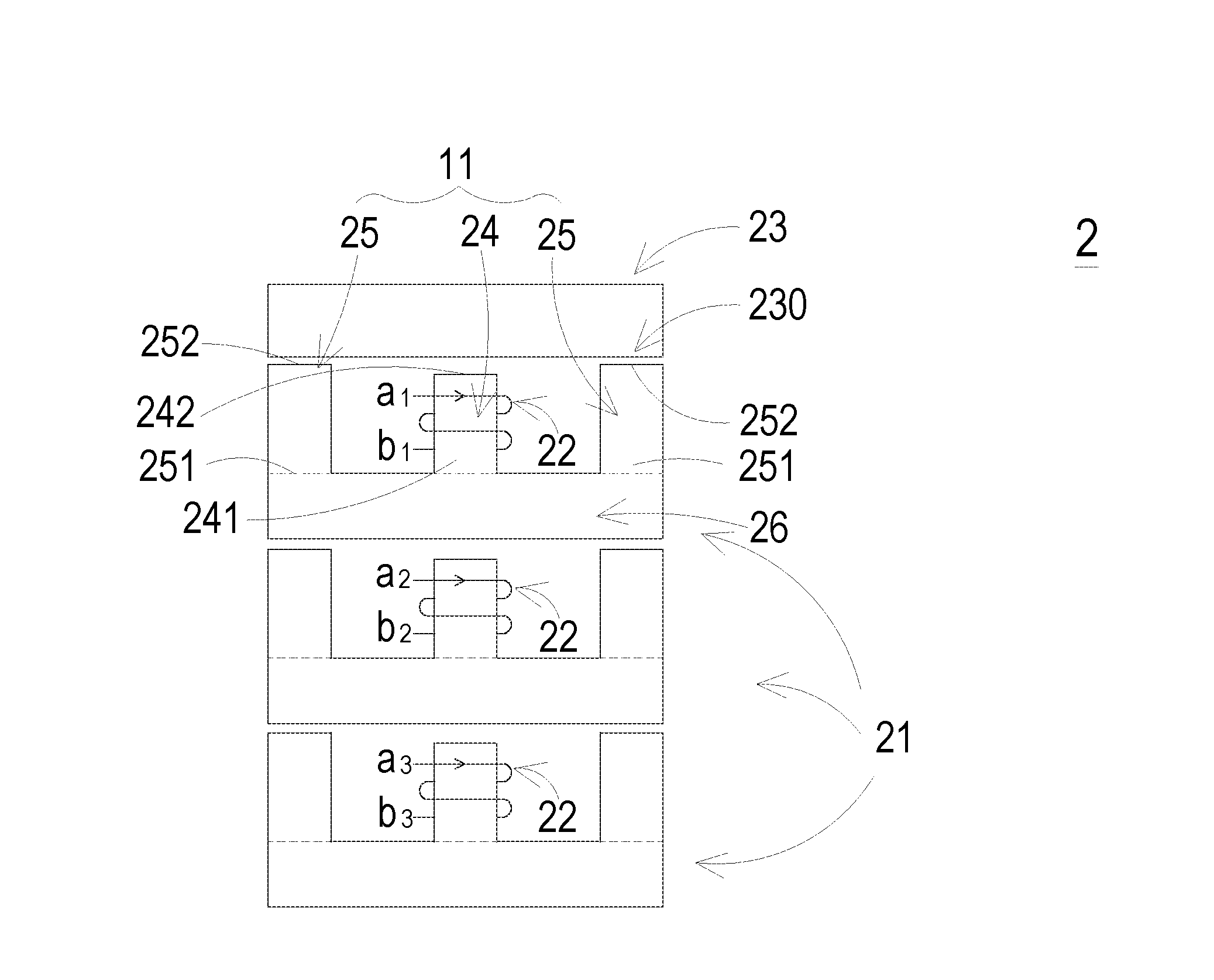
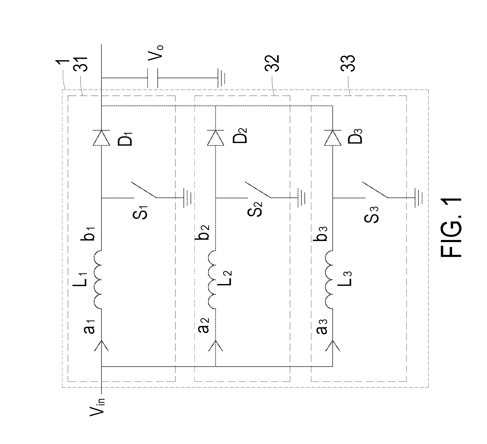
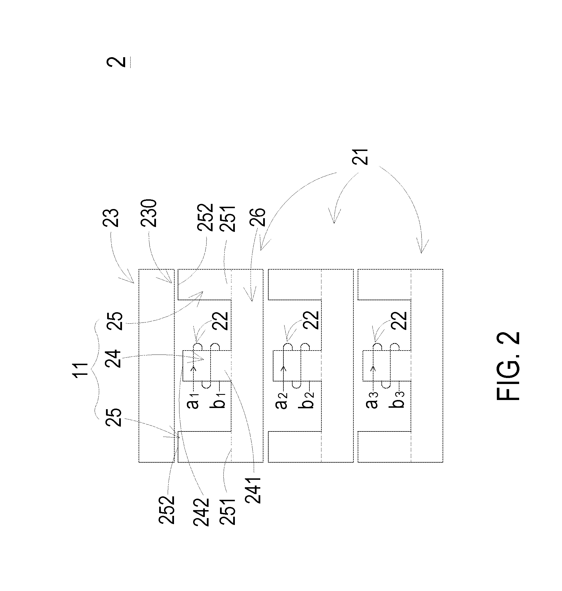
[0023]FIG. 1 is a schematic circuit diagram illustrating a power supply system according to the present invention. FIG. 2 schematically illustrates a magnetic assembly used in the power supply system of FIG. 1. As shown in FIGS. 1 and 2, the power supply system 1 comprises plural converters, which are connected with each other in parallel. Preferably but not exclusively, plural converters comprises a first converter 31, a second converter 32 and a third converter 33. These converters 31, 32 and 33 receive an input voltage Vin and converting the input voltage Vin into an output voltage Vo. Preferably but not exclusively, the converters 31, 32 and 33 are boost converters.

[0024]In this embodiment, the first converter 31 comprises a first magnetic element, a first switch element S1 and a first diode D1. The first magnetic element corresponds to the inductor or the transformer of the first converter 31. For example, in case that the first converter 31 is a boost converter, the first magn...

second embodiment

[0042]FIG. 8 is a schematic circuit diagram illustrating a power supply system according to the present invention. FIG. 9 schematically illustrates a magnetic assembly used in the power supply system of FIG. 8. As shown in FIGS. 8 and 9, the power supply system 7 comprises plural converters, which are connected with each other in parallel. Preferably but not exclusively, plural converters comprises a first converter 71, a second converter 72 and a third converter 73. These converters 71, 72 and 73 receive an input voltage Vin and converting the input voltage Vin into an output voltage Vo. Preferably but not exclusively, the converters 71, 72 and 73 are LLC resonant converters.

[0043]In this embodiment, the first converter 71 comprises a first switch element S11 a second switch element S12, a capacitor C1, a first magnetic element, a second magnetic element, a first diode D11 and a second diode D12. The circuitry configurations of the second converter 72 and the third converter 73 are...


PUM

PropertyMeasurementUnit
magneticaaaaaaaaaa
magnetic fluxesaaaaaaaaaa
lengthaaaaaaaaaa

Abstract

A magnetic assembly includes plural first magnetic cores, plural coil windings and a second magnetic core. Each of the plural first magnetic cores includes plural legs and a first connection part. The first connection part is connected with first terminals of the plural legs. The first connection part of the first magnetic core at an upper position is located adjacent to second terminals of the plural legs of the adjacent first magnetic core at a lower position. Each coil winding is wound around at least one leg of the plural legs of the corresponding first magnetic core so as to form a magnetic element of the corresponding converter. The second magnetic core is stacked over the plural first magnetic cores. The second magnetic core is located adjacent to the second terminals of the legs of the topmost first magnetic core.

Description

FIELD OF THE INVENTION[0001]The present invention relates to a magnetic assembly, and more particularly to a magnetic assembly with reduced magnetic loss, volume, weight and cost. The present invention also relates to a power supply system with the magnetic assembly.BACKGROUND OF THE INVENTION[0002]Generally, plural converters are connected with each other in parallel in a power supply system when high power is required. Each converter comprises at least one magnetic element such as a transformer or an inductor. The magnetic element comprises a magnetic core and a coil winding. The coil winding is wound around the magnetic core to form a closed magnetic flux path. Consequently, the magnetic element is produced.[0003]Since the magnetic element occupies large fractions of volume and weight of the overall power supply system, it is an important issue to reduce the volume and weight of the magnetic element in order to increase the power density of the power supply system. However, since...

Claims


Application Information

Patent Timeline
Patent Type & Authority Applications(United States)
IPC IPC(8): H01F3/10H02M3/156H01F37/00
CPCH01F3/10H02M3/156H01F37/00H02M3/1584H01F27/00
Inventor LU, ZENGYIYAN, YAJIANGYANG, HAIJUNSUN, JUN
Owner DELTA ELECTRONICS SHANGHAI CO LTD
Why Eureka
Try Eureka