Electronically controlled hydraulic swing system

a swing system and electric control technology, applied in soil shifting machines/dredgers, mechanical equipment, servomotors, etc., can solve the problems of high cost of specialized spool valves, inability to provide off-the-shelf spool valves, and difficulty in adjusting the actuation signal, so as to increase and decrease the magnitude of actuation signalt, increase and decrease the effect of actuation signal

Active Publication Date: 2017-01-19
MANITOWOC CRANE CO LLC
View PDF0 Cites 1 Cited by
  • Summary
  • Abstract
  • Description
  • Claims
  • Application Information

AI Technical Summary

Benefits of technology

[0018]Another embodiment of the hydraulic circuit includes at least one tank provides a source of hydraulic fluid to and receiving hydraulic fluid from the hydraulic circuit. At least one hydraulic pump is connected to the at least one tank and provides a flow of hydraulic fluid to the hydraulic circuit at an initial pressure. The hydraulic circuit includes a first valve and at least a second valve. The first and second valve each includes at least one inlet port connected to the hydraulic pump. The first outlet port of each of the first and second valves are configured to reduce an initial pressure to a first pressure and / or a second pressure downstream of the first valve and the second valve, respectively. The first valve and the second valve also include at least a second outlet port connected to a reservoir tank. A hydraulic motor is connected to the first outlet port of the first valve, which operates the hydraulic motor in a first direction. The hydraulic motor also is connected to the first outlet port of the second valve, which operates the hydraulic motor in a second direction.
[0019]An embodiment of a lift crane includes a lower portion, an upper portion that includes a boom mounted thereto, and a swing bearing that rotatably couples the lower portion to the upper portion. A hydraulic circuit for use on the crane includes a first valve, a second valve, and at least a third valve. The second and third valve each includes at least one inlet port connected to a first outlet port of the first valve. The first outlet port of each of the second and third valves are configured to reduce a first pressure to a second pressure and / or a third pressure downstream of the second valve and the third valve, respectively. The second valve and the third valve also include at least a second outlet port connected to a reservoir tank. A hydraulic motor is connected to the first outlet port of the second valve, which operates the hydraulic motor to rotate the upper portion relative to the lower portion in a first direction. The hydraulic motor also is connected to the first outlet port of the third valve, which operates the hydraulic motor to rotate the upper portion relative to the lower portion in a second direction. At least one tank provides a source of hydraulic fluid to and receiving hydraulic fluid from the hydraulic circuit. At least one hydraulic pump is connected to the at least one tank and provides a flow of hydraulic fluid to the hydraulic circuit at an initial pressure.
[0020]An embodiment of a control system for a hydraulic motor in a construction machine includes at least one power source that includes an output sensor to detect an output of the power source and to generate an output signal reflective of the output. A hydraulic circuit for use on a construction machine, such as a crane, includes a first valve, a second valve, and at least a third valve. The second and third valve each includes at least one inlet port connected to a first outlet port of the first valve. The first outlet port of each of the second and third valves are configured to reduce a first pressure to a second pressure and / or a third pressure downstream of the second valve and the third valve, respectively. The second valve and the third valve also include at least a second outlet port connected to a reservoir tank. At least one of the second valve and the third valve is an electrically actuated valve configured to receive an actuation signalt that adjusts the valve in proportion to a magnitude of an actuation signalt, thereby providing a variable decrease in the at least one of said second pressure and said third pressure. A hydraulic motor is connected to the first outlet port of the second valve, which operates the hydraulic motor in a first direction. The hydraulic motor also is connected to the first outlet port of the third valve, which operates the hydraulic motor in a second direction. At least one tank provides a source of hydraulic fluid to and receiving hydraulic fluid from the hydraulic circuit. At least one hydraulic pump is connected to the at least one tank and provides a flow of hydraulic fluid to the hydraulic circuit at an initial pressure.
[0021]The control system also includes an input device that generates an input signal reflective of a position of the input device as an operator manipulates the input device. A memory storage device is configured to store an operating program that calculates the actuation signalt as a function of at least one of the input signal; the output signal; an actuation signalt-1; a first database that correlates said input signal relative to time; a second database that correlates the actuation signalt-1 to the input signal; a first gain that allows an operator to selectively increase and decrease a magnitude of the actuation signalt relative to the input signal; and a second gain that selectively increases and decreases the magnitude of the actuation signalt relative to the output signal.
[0022]The control system also includes a controller configured to receive at least one of the input signal from the input device and the output signal from the power source. The controller additionally runs the operating program and transmits the actuation signalt to at least one of the second valve and the third valve.
[0023]These and other advantages, as well as the invention itself, will become more easily understood in view of the attached drawings and apparent in the details of construction and operation as more fully described and claimed below. Moreover, it should be appreciated that several aspects of the invention can be used with other types of cranes, machines or equipment.

Problems solved by technology

These spool valve based systems posed several challenges, however.
First, an off-the-shelf spool valve typically was not available for a given application.
Understandably, these specialized spool valves typically were quite costly.
Further, by nature of the spool and manufacturing tolerances, the valves often had imprecise flow rates and suffered from leakage across the valve at what were ostensibly no flow conditions.
In addition, the manufacturing imperfections increased the possibility of uneven movements when changing from rotating in one direction to the other.
Such uneven movements typically were the outward manifestation of pressure spikes within the hydraulic circuit, pressure spikes that pose an elevated risk of damaging the hydraulic circuit.
The open center spool valve, however, led to inconsistent starts.
Unfortunately, the trade-off was less satisfactory performance during counter-slewing, including abrupt shifts.
Regardless of the specific type of spool valve, collectively these issues lead to crane-specific hydraulic circuits that require individual calibration of the control systems.
These issues typically prevented the ability to achieve perfectly symmetric flow in each portion of the hydraulic circuit that controls the each direction of rotation of the hydraulic motor.
While some of this might result might be accounted for in the (often crane-specific) calibration of the hydraulic circuit, it nonetheless poses a challenge for the crane operator who must retain awareness about the crane-specific issues with its performance.

Method used


Image

  • Electronically controlled hydraulic swing system
  • Electronically controlled hydraulic swing system
  • Electronically controlled hydraulic swing system

Examples


Embodiment Construction

[0031]The present invention will now be further described. In the following passages, different aspects of the embodiments of the invention are defined in more detail. Each aspect so defined may be combined with any other aspect or aspects unless clearly indicated to the contrary. In particular, any feature indicated as being preferred or advantageous may be combined with any other feature or features indicated as being preferred or advantageous.

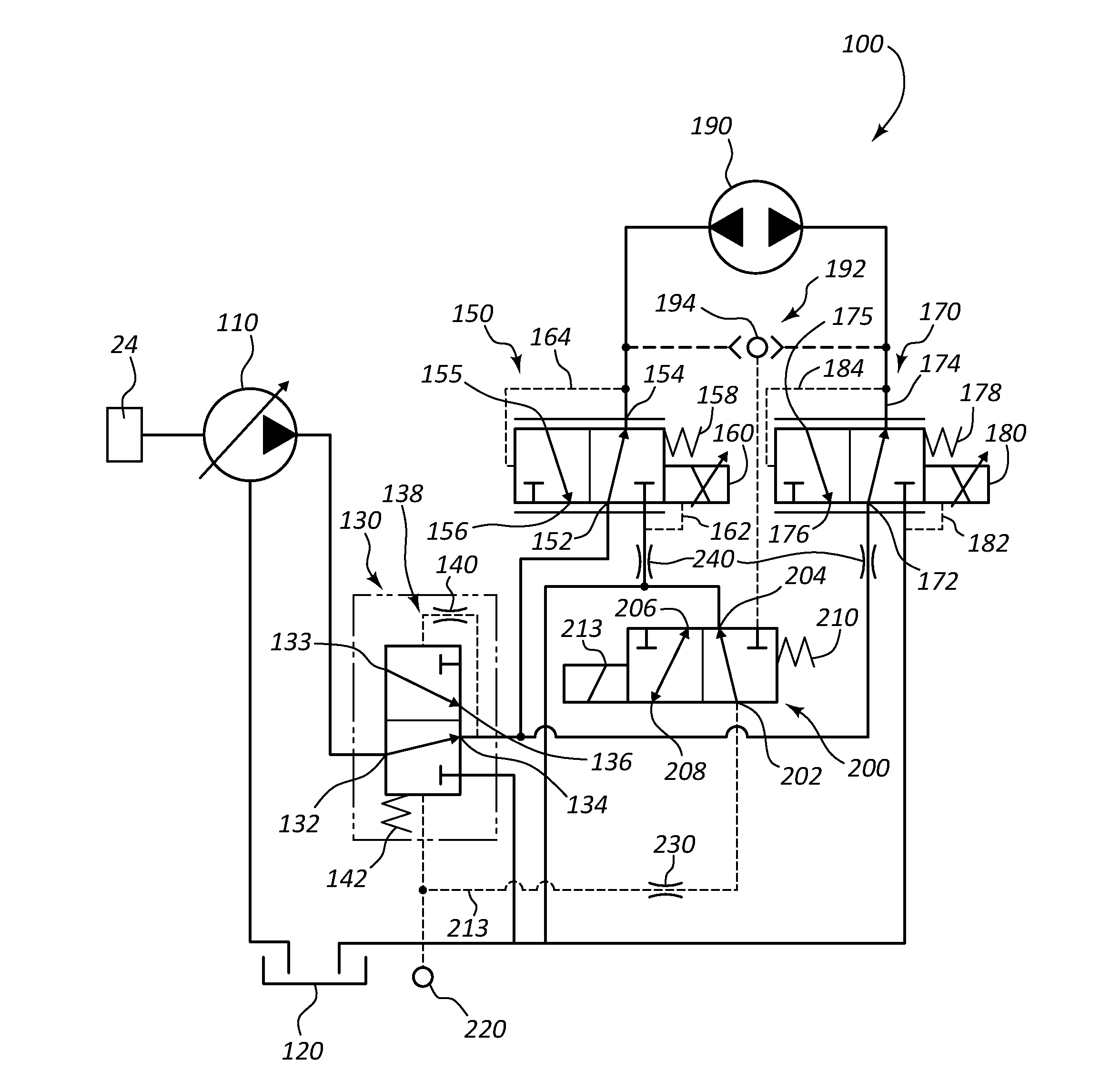
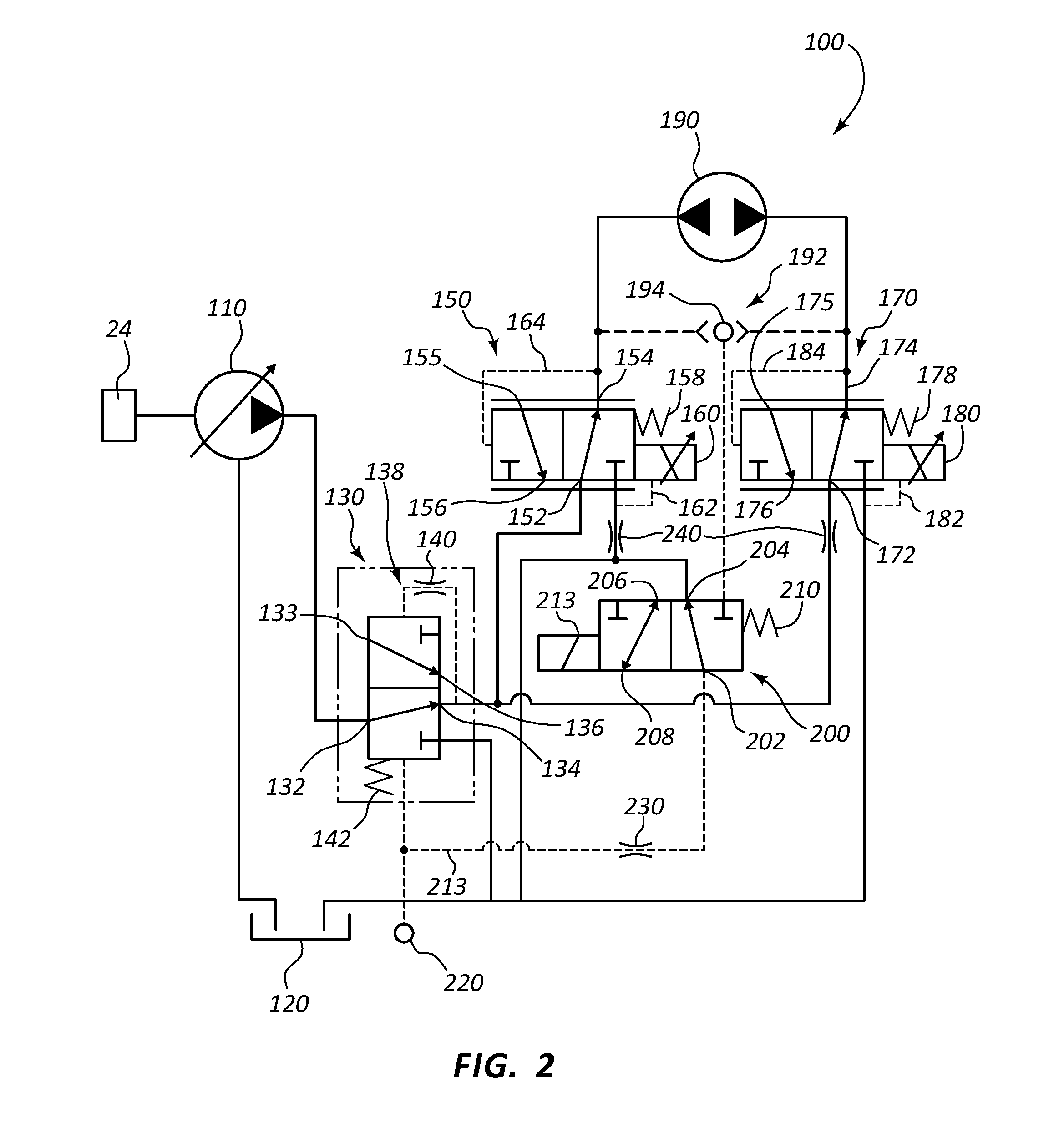
[0032]In addition, the figures illustrate various hydraulic circuits in the standard representational format. The physical embodiment might appear much different than the representational format, but the relevant positions and connections in the physical embodiment will reflect those in the figures. For example, it may be said that a pressure sensor is connected to an outlet. One of skill in the art will understand that in the physical embodiment the connection is a hydraulic connection. The sensor and the outlet may be, but not necessarily,...


PUM


Abstract

A hydraulic circuit for use on a construction machine includes a first valve, a second valve, and at least a third valve. The second and third valve each includes at least one inlet port connected to a first outlet port of the first valve. The first outlet port of each of the second and third valves are configured to reduce a first pressure to a second pressure and/or a third pressure downstream of the second valve and the third valve, respectively. The second valve and the third valve also include at least a second outlet port connected to a reservoir tank. A hydraulic motor is connected to the first outlet port of the second valve, which operates the hydraulic motor in a first direction. The hydraulic motor also is connected to the first outlet port of the third valve, which operates the hydraulic motor in a second direction.

Description

PRIORITY CLAIM[0001]The present application is a 371 national phase application of International Application No. PCT / US2015 / 018469, filed Mar. 3, 2015 and titled Electronically Controlled Hydraulic Swing System, which in turn claims priority to and the benefit of U.S. Provisional Patent Application Ser. No. 61 / 947,421 filed Mar. 4, 2014 and titled Electronically Controlled Hydraulic Swing System, the disclosures of which are incorporated in their entireties by this reference.BACKGROUND[0002]The present application relates to construction equipment, such as cranes. In particular, the present application relates to a construction machines that include an electronically controlled hydraulic circuit. In the instance of cranes, the hydraulic circuit operates to control the rotation or swing of an upper portion of the crane relative to a lower portion.[0003]Previous cranes typically used a hydraulic circuit that employed what are known as spool valves to control the hydraulic motor that t...

Claims


Application Information

Patent Timeline
Patent Type & Authority Applications(United States)
IPC IPC(8): B66C23/86F15B13/04F15B11/08B66C23/36F15B1/26
CPCB66C23/86B66C23/36F15B1/26F15B2211/255F15B13/0401F15B2211/20546F15B11/08E02F9/123E02F9/2296F15B2211/3057F15B2211/7058
Inventor BENTON, JOHN F.HARBOLD, MARK A.SNIDER, TODDPEIFFER, DAVID R.
Owner MANITOWOC CRANE CO LLC
Why Eureka
Try Eureka