
Touch display device

a display device and touch technology, applied in the field of touch display devices, can solve the problems of increasing production costs, and achieve the effect of reducing the size of the peripheral region and the size of the driving integrated circui

Inactive Publication Date: 2017-01-19
INNOLUX CORP
View PDF7 Cites 16 Cited by
  • Summary
  • Abstract
  • Description
  • Claims
  • Application Information

AI Technical Summary

Benefits of technology

The invention is a touch display device that reduces the size of the driving integrated circuit and the peripheral region of the touch display panel. This is achieved by configuring multiplexers in the driving integrated circuit that integrate display data and touch signals, and by enabling these to perform switching operations on the touch display panel. This reduces the number of output leads required, reduces the layout area for transmission wires, and lowers the cost of the driving integrated circuit. Additionally, the use of multiplexers reduces the number of leads, connecting wires, and bonding pads between the driving integrated circuit and the touch display panel, thereby reducing the area required and overall production cost.

Problems solved by technology

As a result, when the number of the touch signals in the touch display device increases, the number of leads in the driving integrated circuit and the size of the peripheral region on the touch display panel will also increase in correspondence, thereby causing the production cost to increase.

Method used


Image

  • Touch display device
  • Touch display device
  • Touch display device

Examples


Embodiment Construction

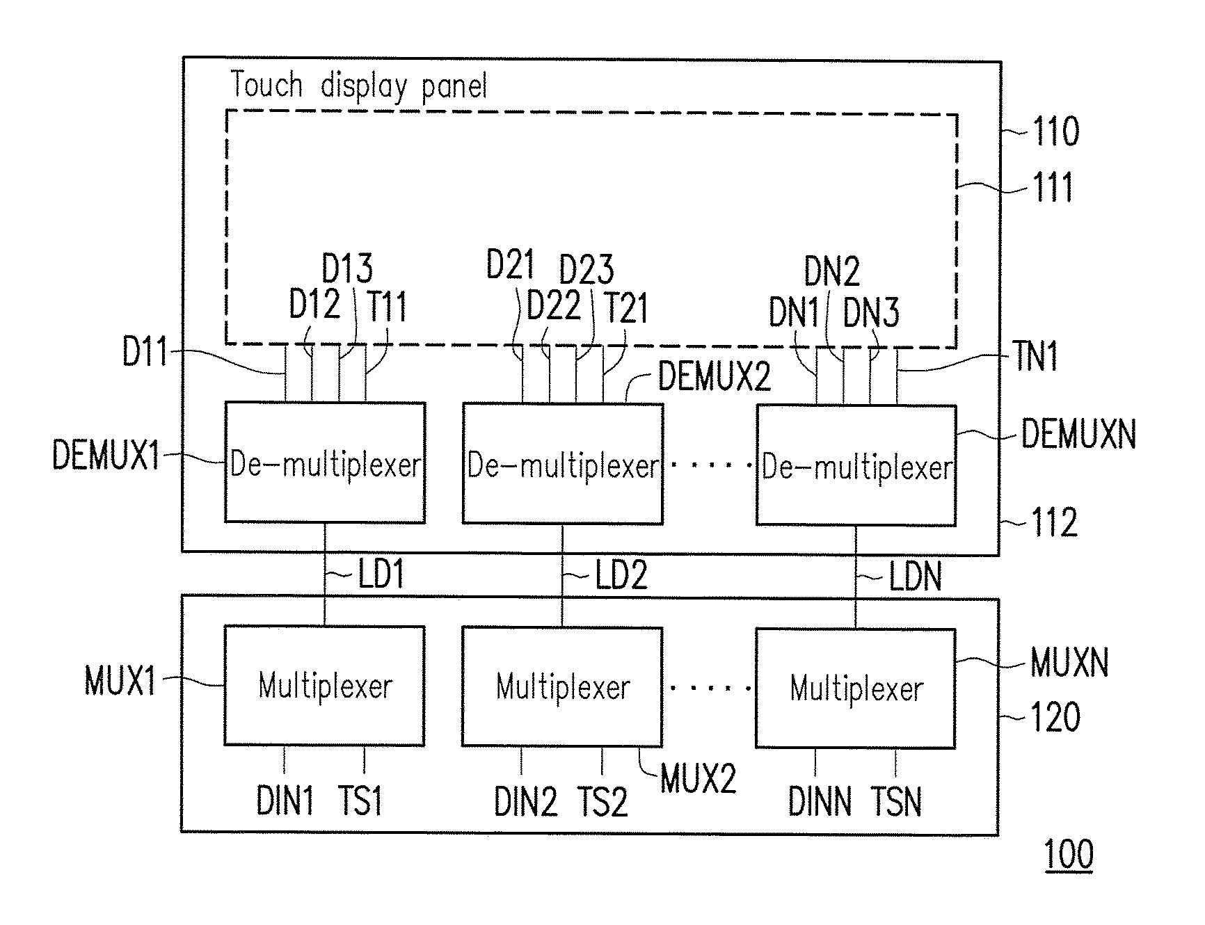
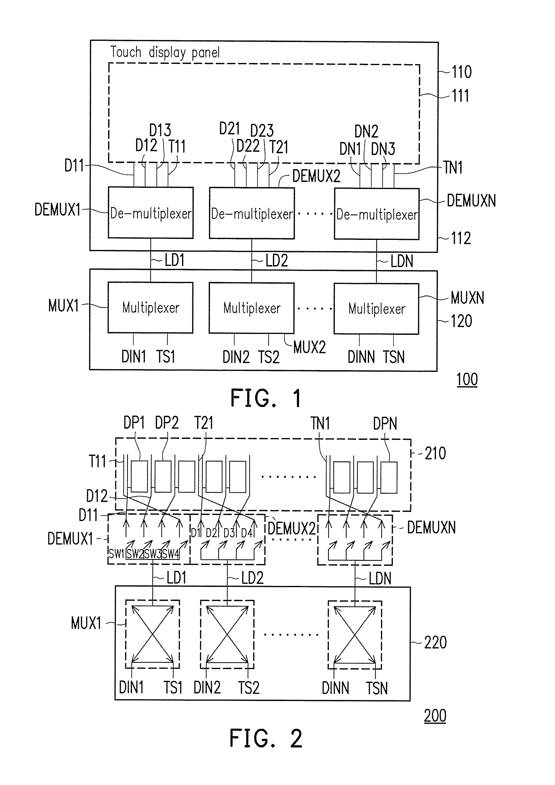
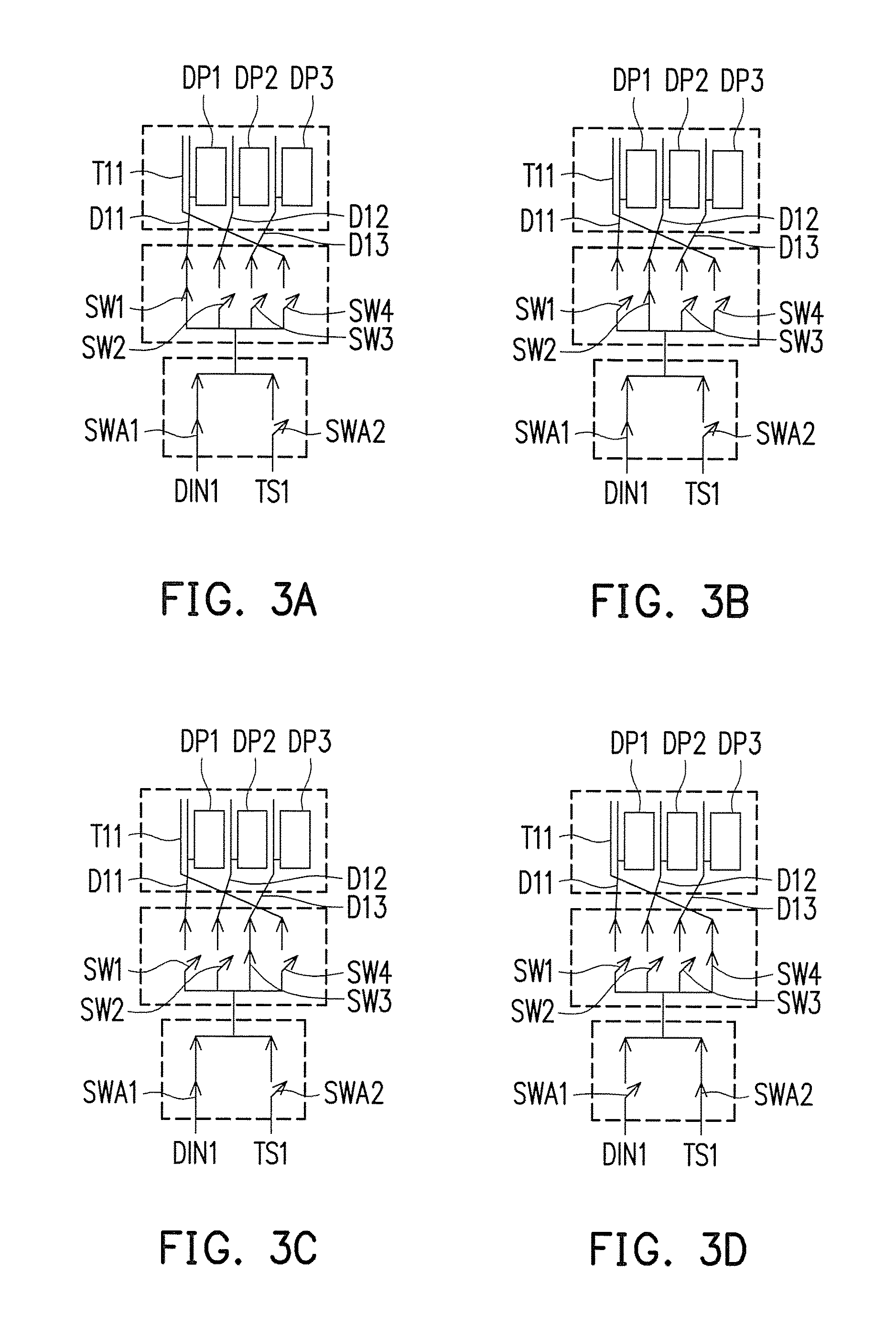
[0018]Referring to FIG. 1, FIG. 1 is a schematic diagram illustrating a touch display device 100 according to an embodiment of the invention. The touch display device 100 includes a touch display panel 110, a plurality of de-multiplexers DEMUX1˜DEMUXN and a driving integrated circuit 120. The driving integrated circuit 120 includes a plurality of multiplexers MUX1˜MUXN. In one embodiment, the de-multiplexers DEMUX1˜DEMUXN are disposed on a peripheral region 112 of the touch display panel 110, and a plurality of output terminals of the de-multiplexers DEMUX1˜DEMUXN may be electrically connected to a plurality of display data transmitting wires D11˜D13, D21˜D23, . . . DN1˜DN3 and a plurality of touch data transmitting wires T11˜TN1 on the touch display panel 110, respectively. Using the de-multiplexer DEMUX1 as an example, the output terminals of the de-multiplexer DEMUX1 are electrically connected to the display data transmitting wires D11˜D13 and the touch data transmitting wire T11...


PUM


Abstract

A touch display device comprising a touch display panel, a first de-multiplexer and a driving integrated circuit (IC) is provided. The touch display panel includes a plurality of first display data transmitting wires and a touch data transmitting wire. The first de-multiplexer includes a plurality of first output terminals and a first input terminal. The driving IC includes a multiplexer including a second output terminal. The first output terminals of the first de-multiplexer are electrically connected to the first display data transmitting wires and the touch data transmitting wire, respectively. The second output terminal of the multiplexer is electrically connected to the first input terminal of the first de-multiplexer through a first lead.

Description

CROSS-REFERENCE TO RELATED APPLICATION[0001]This application claims the priority benefits of U.S. provisional application Ser. No. 62 / 193,787, filed on Jul. 17, 2015, and Taiwan application serial no. 105106635, filed on Mar. 4, 2016. The entirety of each of the above-mentioned patent applications is hereby incorporated by reference herein and made a part of this specification.BACKGROUND OF THE INVENTION[0002]1. Field of the Invention[0003]The invention relates to a touch display device, and more particularly, to a touch display device capable of reducing lead number of driving integrated circuit (IC) and peripheral region size of touch display panel.[0004]2. Description of Related Art[0005]Along with rapid development of electronic technology, consumer electronic products have become an indispensable part in people's daily life. In order to improve an operational convenience of the electronic products, high-performance touch display devices have become an essential type among the e...

Claims


Application Information

Patent Timeline
IPC IPC(8): G06F3/041G09G3/20
CPCG06F3/0412G09G2310/0297G09G3/2092G06F3/0416G06F3/044G09G2300/0465G06F3/04164G06F3/04166
Inventor TSAI, CHIA-HAOPENG, JEN-CHIEHCHANG, CHIH-HAOCHEN, BO-FENGLIU, TUNG-KAI
Owner INNOLUX CORP
Learn More