Physical Quantity Sensor

a sensor and physical technology, applied in the field of physical quantity sensors, can solve problems such as adversely affecting the measurement accuracy, and achieve the effect of increasing the measurement accuracy of the sensor elemen

Inactive Publication Date: 2017-01-19
HITACHI LTD
View PDF5 Cites 9 Cited by
  • Summary
  • Abstract
  • Description
  • Claims
  • Application Information

AI Technical Summary

Benefits of technology

[0019]According to the invention, since the plurality of lead portions support the sensor element in such a manner that the sensor element does not contact the package substrate and that the transmission of deformation of the package substrate side to the sensor element is suppressed, the influence of deformation of the package substrate on a detection signal of the sensor element is reduced, and thus the measuring accuracy of the sensor element can be increased.

Problems solved by technology

This deformation adversely affects the measuring accuracy for the physical quantity as an original measurement target.

Method used


Image

  • Physical Quantity Sensor
  • Physical Quantity Sensor
  • Physical Quantity Sensor

Examples


example 1

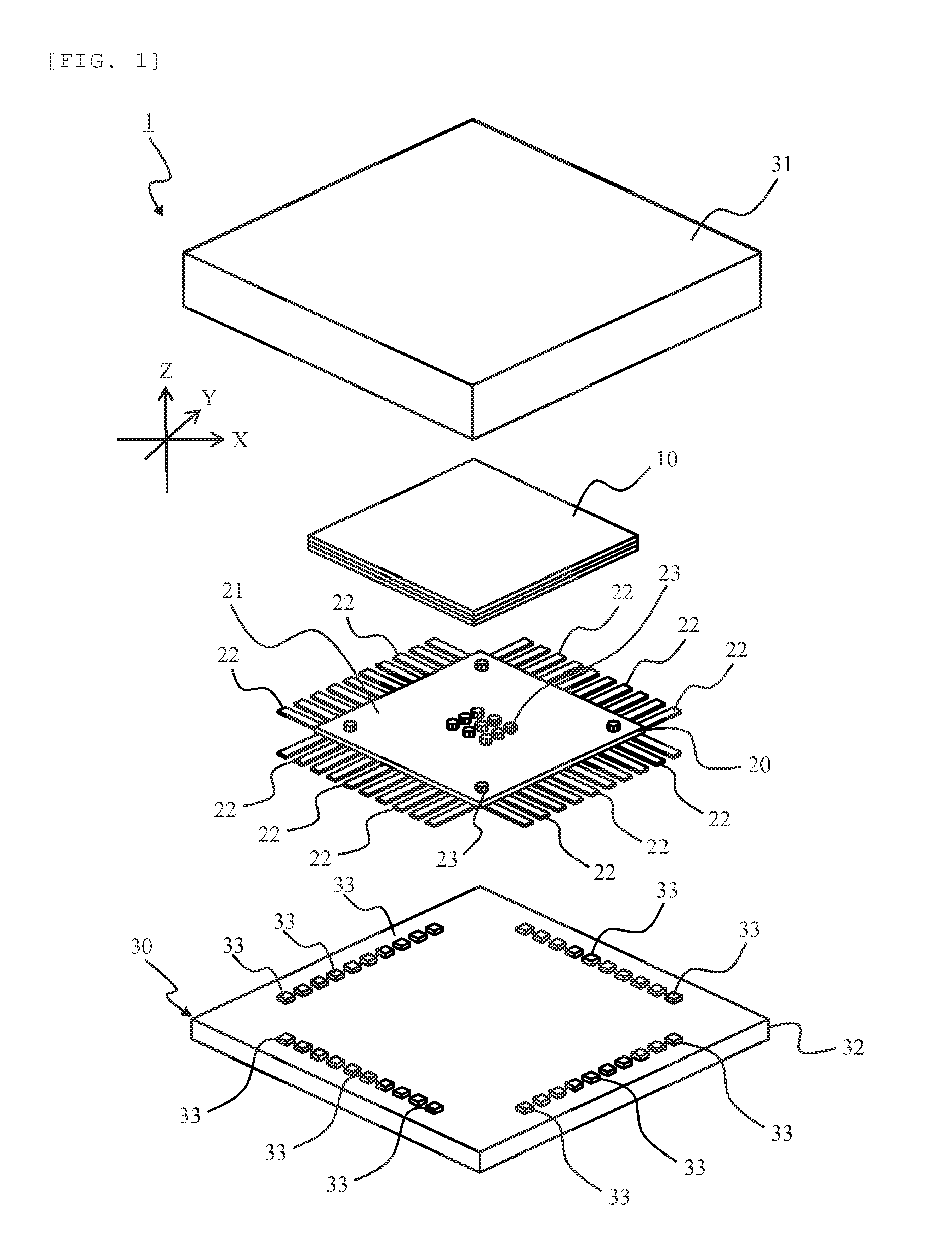
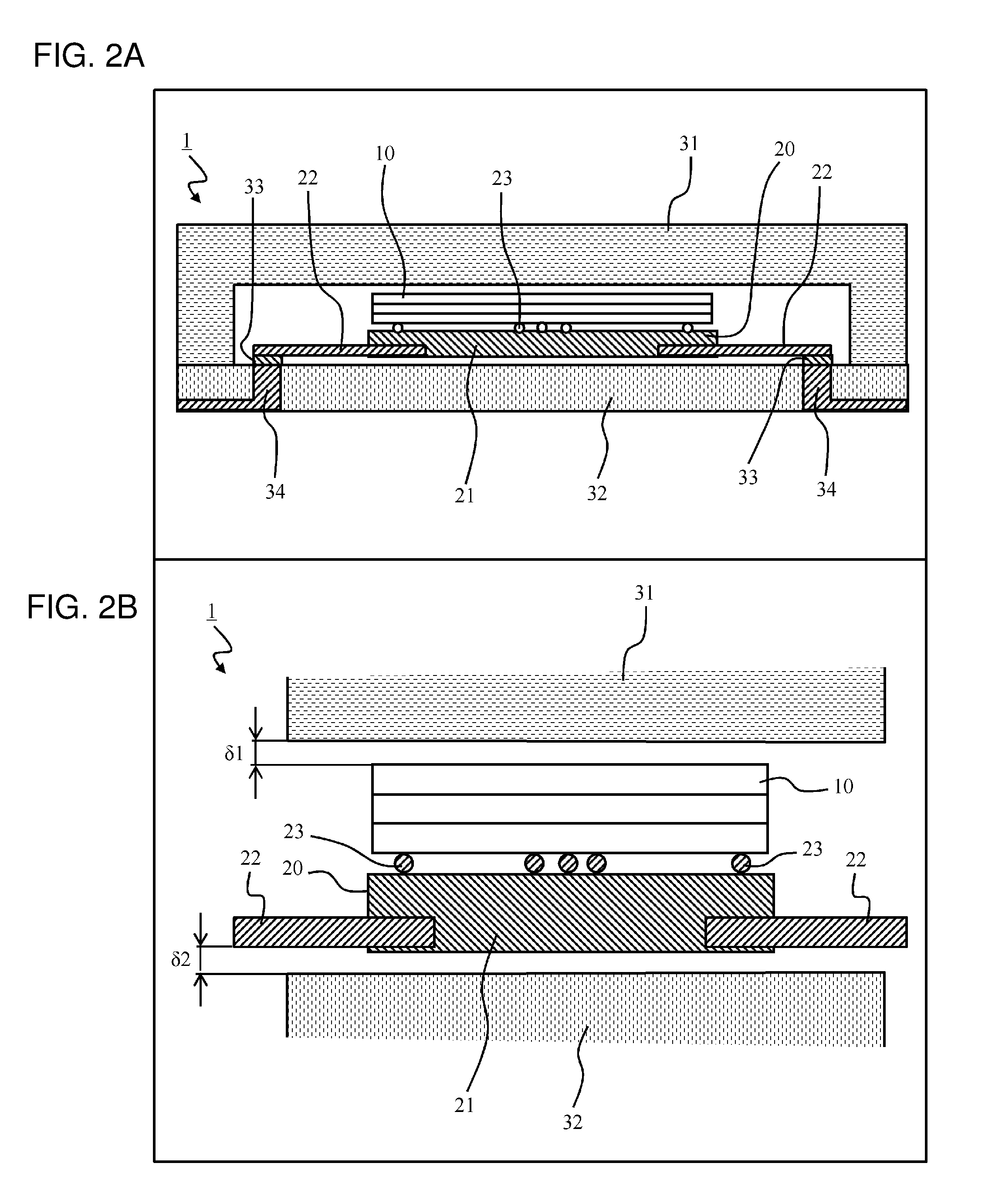
[0035]A first example will be described using FIGS. 1 and 2. FIG. 1 is an exploded perspective view of a physical quantity sensor 1 according to the example. FIG. 2 are cross-sectional views of the physical quantity sensor.

[0036]The physical quantity sensor 1 is, for example, a device that detects a predetermined physical quantity (physical quantity as a measurement target) such as acceleration or angular velocity, and outputs a signal. The physical quantity sensor 1 is configured to include, for example, the sensor chip 10, the lead substrate 20, and the package substrate 30.

[0037]When a physical quantity as a measurement target is applied, a three-dimensional structure in the interior of the sensor chip 10 is deformed, and the sensor chip 10 outputs an electrical signal. The sensor chip 10 uses a change in capacitance or a change in resistance in response to the deformation of the three-dimensional structure to convert the deformation into an electrical signal. The sensor chip 10 ...

example 2

[0053]A second example will be described with reference to FIGS. 3 and 4. The following examples including the example correspond to modified examples of the first example, and therefore, the differences from the first example will be mainly described. A physical quantity sensor 1A of the example incorporates the amplifier circuit board 50 therein. FIG. 3 is an exploded perspective view of the physical quantity sensor 1A. FIG. 4 are cross-sectional views of the physical quantity sensor 1A.

[0054]The physical quantity sensor 1A is configured to include the sensor chip 10, the lead substrate 20, a package substrate 30, and the amplifier circuit board 50. The amplifier circuit board 50, which is an example of the “predetermined board” that processes a signal from the sensor chip 10, amplifies a signal of the sensor chip 10 and outputs the signal. Hereinafter, the amplifier circuit board 50 is sometimes abbreviated as the circuit board 50.

[0055]The circuit board 50 is formed into a squar...

example 3

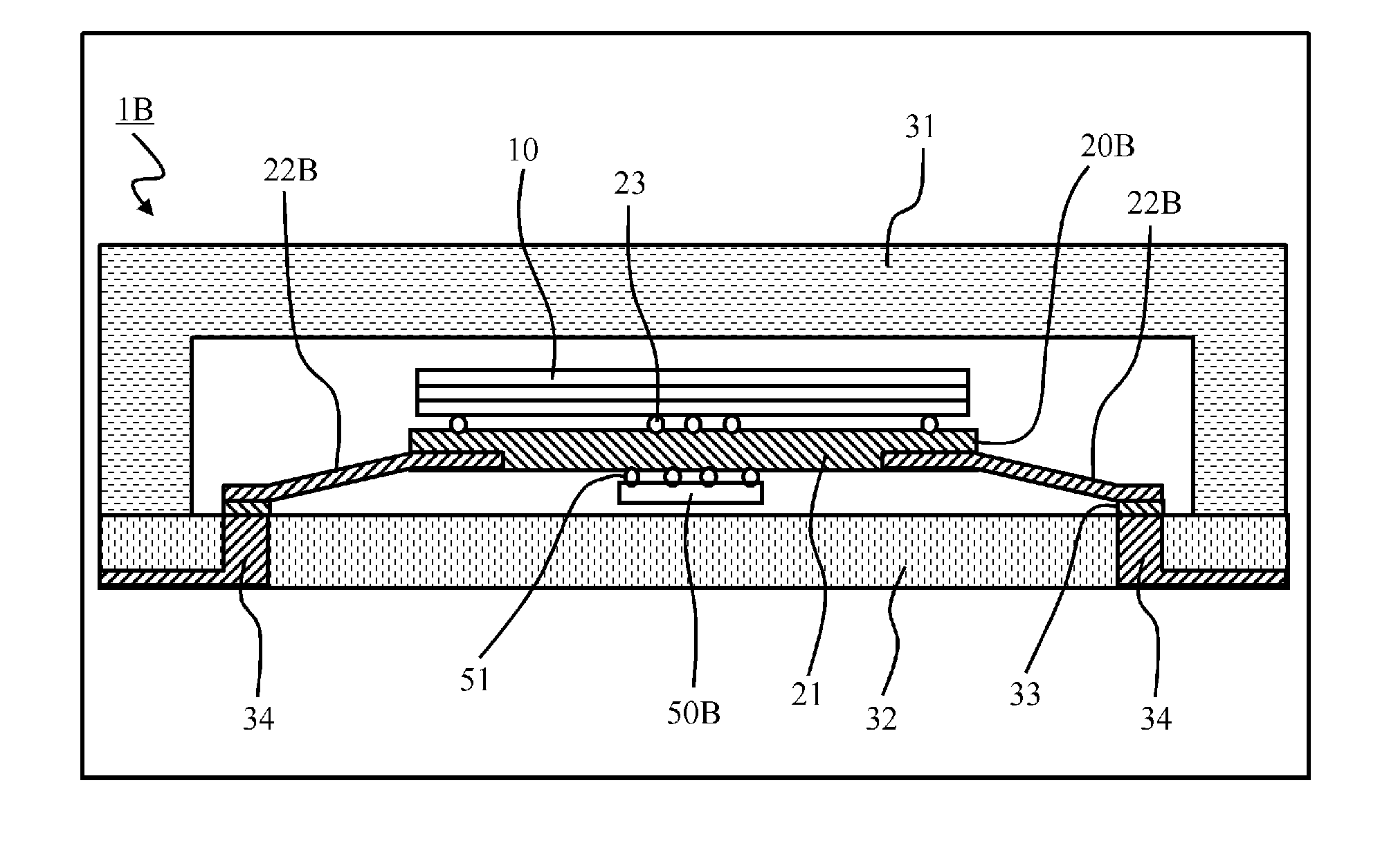
[0059]A third example will be described using FIGS. 5 and 6. A physical quantity sensor 1B of the example includes a circuit board 50B mounted on the lower surface of the electrode substrate 21 of a lead substrate 20. Further, in the physical quantity sensor 1B of the example, leads 22 are slightly bent so as to forma space for disposing the circuit board 50B between the lower surface of the electrode substrate 21 and the upper surface of the substrate portion 32. FIG. 5 is an exploded perspective view of the physical quantity sensor 1B. FIG. 6 are cross-sectional views of the physical quantity sensor 1B.

[0060]The physical quantity sensor 1B is configured to include the sensor chip 10, the lead substrate 20B, the package substrate 30, and the circuit board 50B. The leads 22B are bent obliquely downward and extracted, as shown in FIG. 6, from the four sides of the electrode substrate 21 of the lead substrate 20B.

[0061]When the electrode plate 21 is assumed as a reference horizontal p...


PUM

PropertyMeasurementUnit
physical quantityaaaaaaaaaa
rigidityaaaaaaaaaa
stressaaaaaaaaaa

Abstract

To provide a physical quantity sensor in which the influence of deformation of a package substrate on the measuring accuracy of a sensor element can be suppressed. A physical quantity sensor includes a sensor element that detects a predetermined physical quantity and outputs an electrical signal, a plurality of lead portions that are connected to the sensor element, and a package substrate that accommodates the sensor element and the plurality of lead portions. The plurality of lead portions are connected at proximal end sides thereof to the package substrate side, and connected at distal end sides thereof to the sensor element side, and the plurality of lead portions support the sensor element in such a manner that the sensor element does not contact the package substrate and that the transmission of deformation of the package substrate side to the sensor element is suppressed.

Description

TECHNICAL FIELD[0001]The present invention relates to a physical quantity sensor.BACKGROUND ART[0002]Physical quantity sensors whose measurement target is a physical quantity such as acceleration are manufactured using a micro-electro-mechanical systems (MEMS) technique. The physical quantity sensor is, for example, a minute three-dimensional structure that is processed using techniques such as deposition, photolithography, and etching to which a semiconductor manufacturing process is applied. When a signal (pressure, acceleration, angular velocity, etc.) from the outside acts on the three-dimensional structure of the physical quantity sensor, the physical quantity sensor outputs an electrical signal in response to the deformation amount of the three-dimensional structure.[0003]A physical quantity sensor disclosed in PTL 1 is composed of beams, a weight, and detection electrodes. In the physical quantity sensor of PTL 1, when a signal (acceleration, angular velocity) from the outsid...

Claims


Application Information

Patent Timeline
Patent Type & Authority Applications(United States)
IPC IPC(8): H01L23/053G01L9/02G01P15/18G01P3/44H01L23/498B81B7/00
CPCH01L23/053H01L23/49838H01L23/49861B81B7/0058G01P15/18B81B2207/07G01L9/02B81B2201/0235B81B2201/0242B81B2201/0264G01P3/44H01L23/057G01C19/5783G01P1/006G01P1/023G01L9/12H01L2224/16225B81B7/0048
Inventor AONO, TAKANORISEKIGUCHI, TOMONORISHIOTA, TAKASHIKAMADA, YUUDAIISOBE, ATSUSHI
Owner HITACHI LTD
Why Eureka
Try Eureka