Optical sensor system and detecting method for an enclosed semiconductor device module

a technology of optical sensor and semiconductor device, which is applied in the direction of instruments, heat measurement, optical elements, etc., can solve the problems of inability to accurately reflect the operating temperature of the power electronic components, the current sharing measurement such as these is often impractical in commercial implementation, and the current sharing measurement is not satisfactory. to achieve the effect of reducing the stress of optical fibr

Inactive Publication Date: 2011-11-03
VESTAS WIND SYST AS
View PDF5 Cites 10 Cited by
  • Summary
  • Abstract
  • Description
  • Claims
  • Application Information

AI Technical Summary

Benefits of technology

[0017]The use of an optical fibre allows detection without disturbing the operation of the sensitive electronic components in the housing. In addition, the optical fibres are not themselves likely to be damaged by the high operating temperatures within the module.
[0019]In one embodiment, the at least one electronic device is formed as a die, and the optical fibre is attached to the die by heat resistant adhesive, thus ensuring a secure thermal contact and improving the accuracy of the sensor. The heat resistant adhesive may be a glass reinforced epoxy resin.
[0021]In a further embodiment, the optical fibre is coated with a flexible coating layer, which can be used to reduce stresses in the optical fibre caused by difference in the thermal expansion of the fibre and the die. The flexible coating layer can be one or more of silicone, polyimide, non-viscous cream, thermal insulating compound, heat sink paste.
[0025]In conjunction with the sensor system discussed above, the operation of the module can be made more safe and / or efficient. In one example, the controller can be arranged to shut off the power to the power electronics module based on the operating parameter. Additionally, or alternatively, the semiconductor device module control system comprises a cooling system coupled to the controller and operable based on the operating parameter.

Problems solved by technology

There are a number of known methods for measuring the temperature of the components inside a power electronics module such as that shown in FIGS. 1 and 2, however as will be explained below, all methods are currently unsatisfactory and have a number of inherent disadvantages.
Current sharing measurements such as these are often impractical in commercial implementations.
However, due to switching noise in the IGBT 206, in order to measure the thermocouple current, it is often necessary to deactivate the switch, and measure the current immediately afterwards.
In systems which are efficiently cooled, this leads to a measurement that does not accurately reflect the operating temperature of the power electronic components.
However, to operate these devices must necessarily draw some current.
A drawback with these techniques is that they require galvanic connections that extend from the interior of the power electronics module to the exterior for sensing and control purposes.
This can cause interference in the operation of the device, can draw noise out of the module, and can compromise safety if the connections are not correctly isolated.

Method used


Image

  • Optical sensor system and detecting method for an enclosed semiconductor device module
  • Optical sensor system and detecting method for an enclosed semiconductor device module
  • Optical sensor system and detecting method for an enclosed semiconductor device module

Examples


Embodiment Construction

[0040]Generally, the invention involves the provision of an optical fibre sensor system to a enclosed semiconductor device, such as a power electronics module or microprocessor with housing, to monitor its operation.

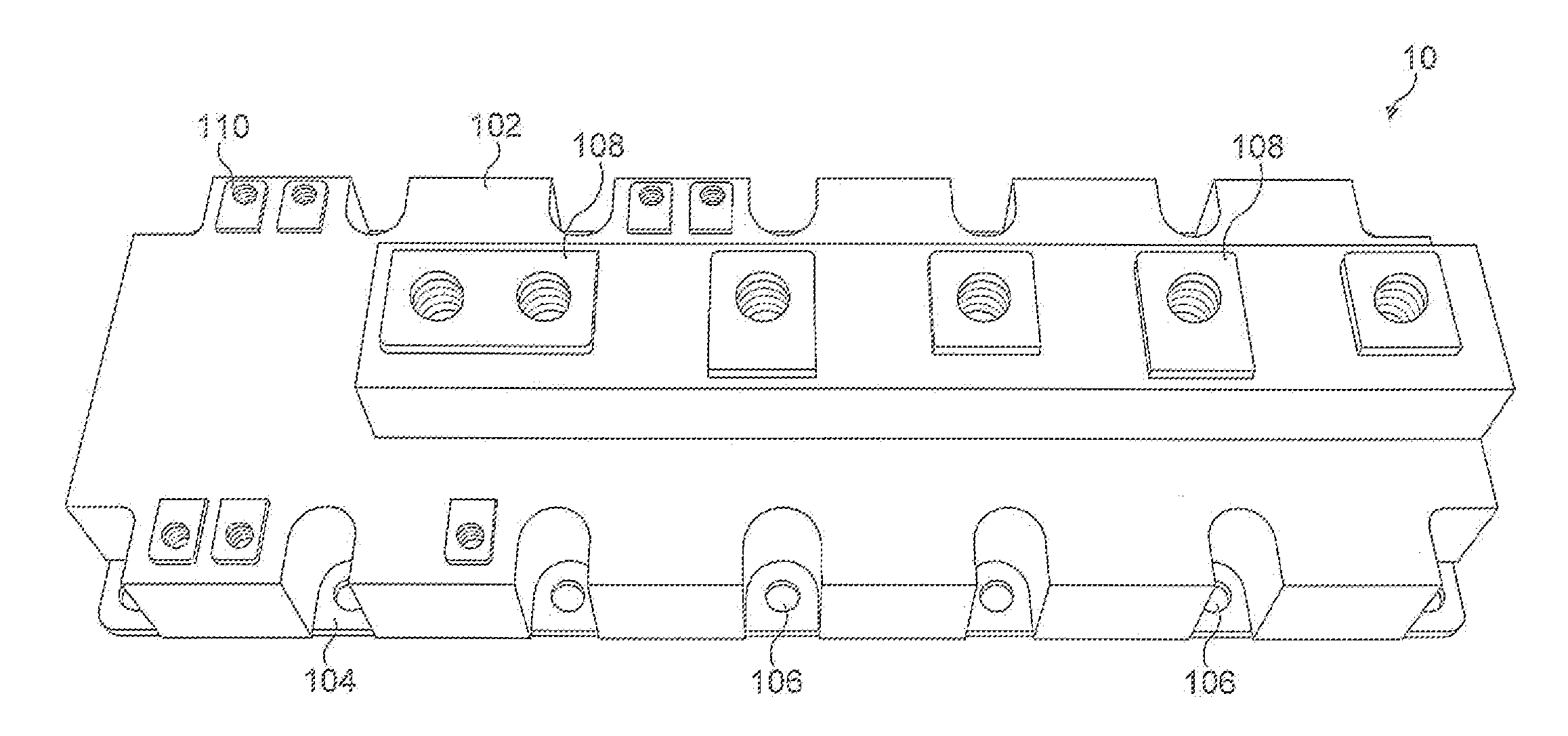
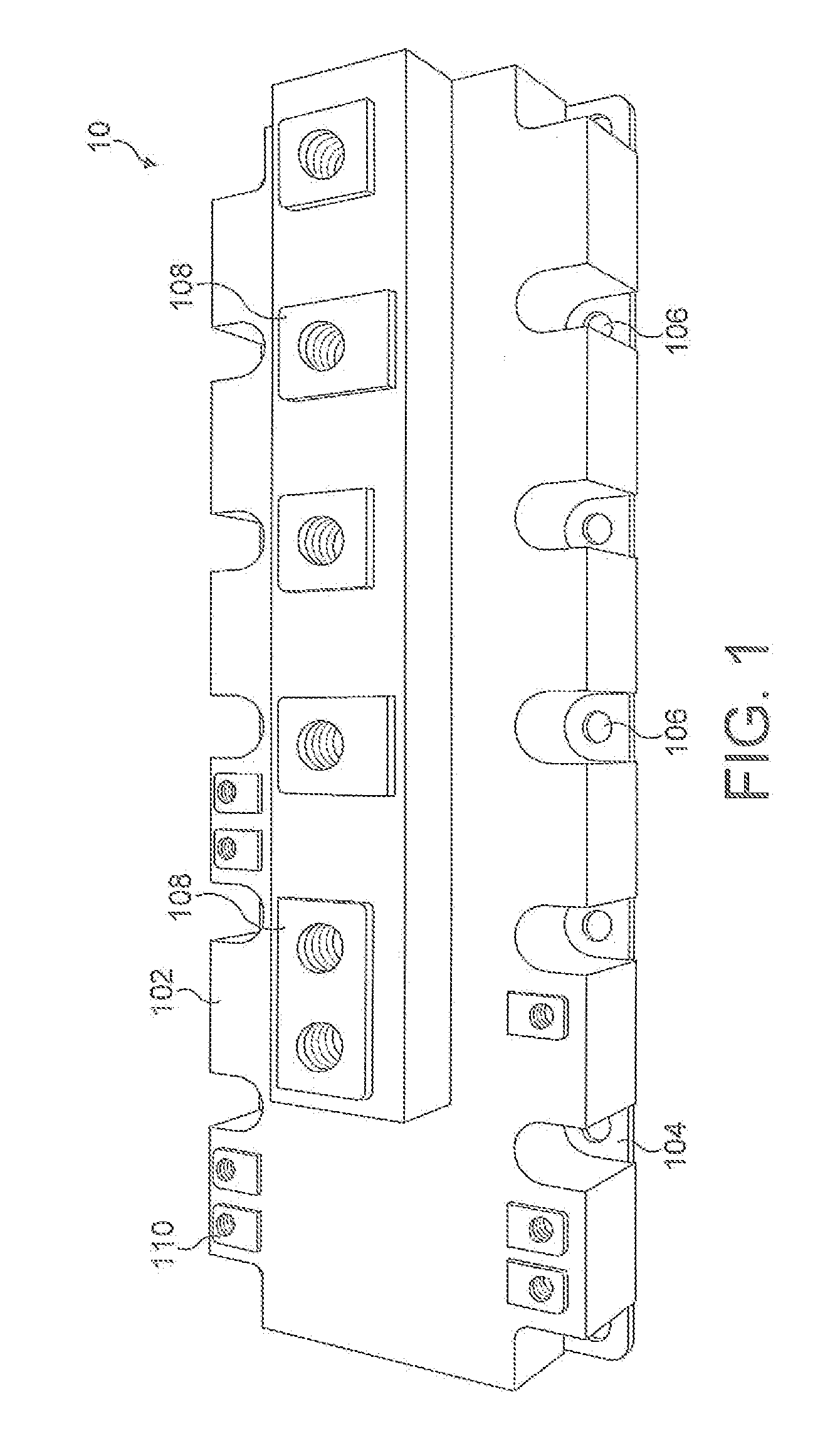
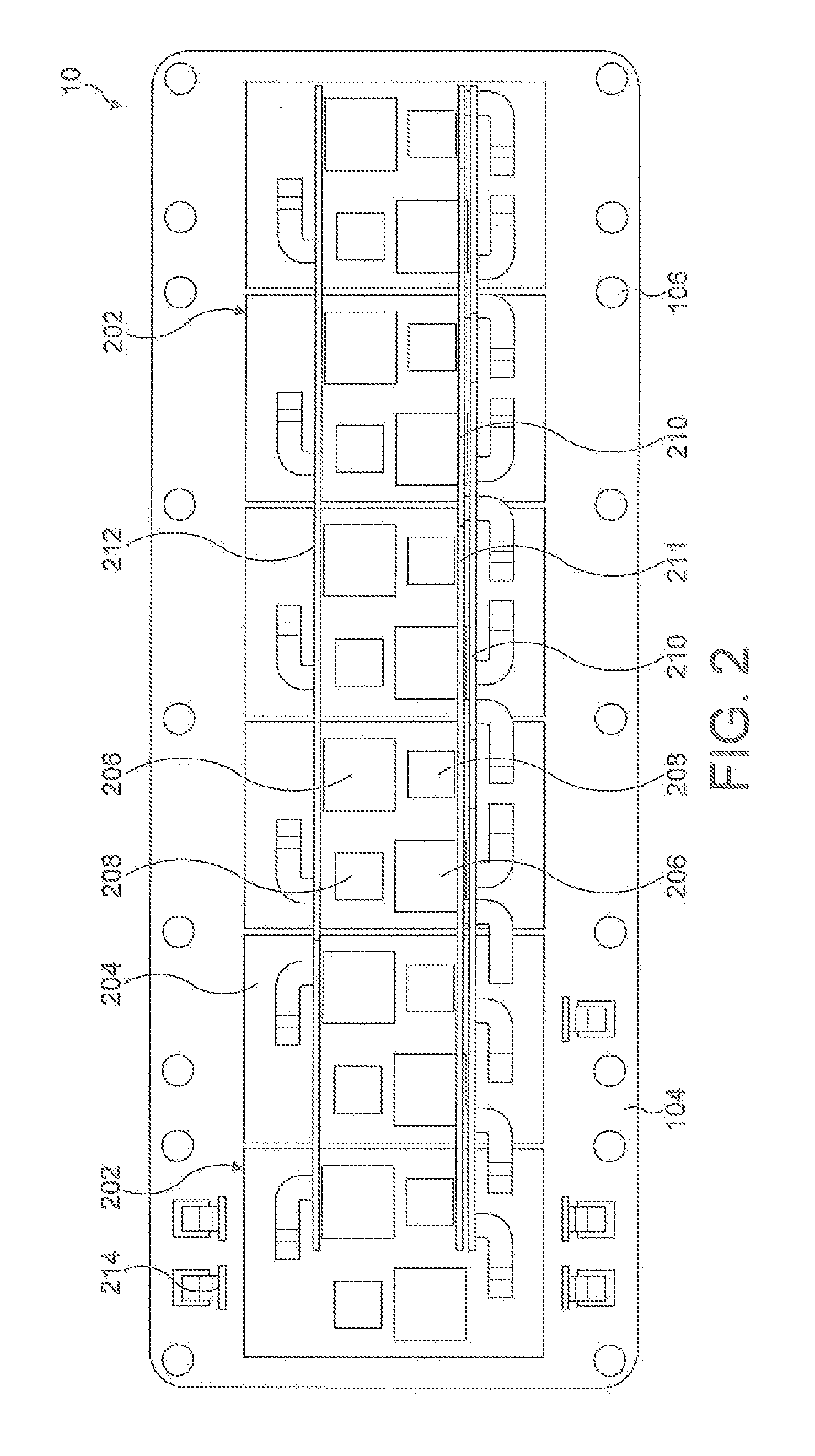
[0041]A particular example of the invention in a power electronics module will now be described with reference to FIG. 3. For the purposes of illustration, the construction of the power electronics module will be assumed to be largely identical to the devices shown in FIGS. 1 and 2. The module 300 has a plastic housing 302 with a copper base plate 304, onto which a DCB 306 is soldered or connected thermally with a suitable thermal interface material. The connection between the base plate and the DCB 306 could also be by so-called sintering processes. The base plate provides a sturdy base for the assembly and assists in spreading the heat from the plurality of active semiconductor devices, known as dies, mounted on the DCB 306.

[0042]The DCB 306 is formed of a ceramic mate...


PUM


Abstract

A sensor system and method for a power electronics module is discussed. The system comprises a optical fibre 318 mounted inside the module housing 302 and connected to an external sensor system 320 (not shown). The optical fibre 318 is arranged so that it lies proximate to one or more semiconductor dies 308 within the housing, and can sense their temperature. The fibre can be connected to the die 308 by glue, mechanical connection, or can in other examples by provided in the underlying support structure such as a DCB (direct copper bonded ceramic structure) or base plate 304. The fibre can contain an optical grating, such as an FBG or LPG, or can operate based on interferometry, to detect temperature or strain.

Description

CROSS-REFERENCE TO RELATED APPLICATIONS[0001]The present application claims the benefit of U.S. Provisional Application No. 61 / 329,790, filed Apr. 30, 2010, and claims priority under 35 U.S.C. §119 to United Kingdom Patent Application GB1007355.9, filed Apr. 30, 2010. The content of each of these applications is hereby incorporated by reference herein in its entirety for all purposes.BACKGROUND[0002]The invention relates to an optical sensor system and detecting method for an enclosed semiconductor device module, and in particular to embodiments for use in a power electronics module or a microprocessor with housing.[0003]A power electronics module is a device that houses a plurality of power system components, such as semiconductor devices often used to switch high currents and voltages. In such applications, the semiconductor devices are often MOSFETs (metal Oxide Semiconductor Field Effect Transistors) or IGBTs (Insulated Gate Bipolar Transistors), as these offer high efficiency a...

Claims


Application Information

Patent Timeline
Patent Type & Authority Applications(United States)
IPC IPC(8): G01B11/16G02B6/00
CPCG01K1/14G01D5/35316G01K11/3206H01L23/34H01L23/3735H01L2224/4846H01L2224/48137H01L2224/49111H01L2224/4917H01L2224/48139H01L2224/8592H01L2224/40225
Inventor HJORT, THOMASGLAVIND, LARS
Owner VESTAS WIND SYST AS
Why Eureka
Try Eureka