Method and device for operating a particle sensor

a particle sensor and sensor element technology, applied in the direction of electrical control, instruments, nuclear elements, etc., can solve the problem of increasing the accumulation rate of particles on the sensor element, and achieve the effect of accurately determining the time of regeneration of the diesel particle filter

Active Publication Date: 2014-02-04
ROBERT BOSCH GMBH
View PDF8 Cites 10 Cited by
  • Summary
  • Abstract
  • Description
  • Claims
  • Application Information

AI Technical Summary

Benefits of technology

[0011]For the sake of improved self-diagnosis and increased sensor accuracy, the object of the invention is to make available a corresponding method which permits an improved method of functioning of the system while avoiding cross sensitivities owing to these shunts.
[0015]In order to avoid shunts between the measuring electrodes over the service life of the particle sensor, which shunts reduce the sensor accuracy, it is usually necessary to make considerable expenditure in terms of the use of corresponding materials and techniques in the fabrication process. With the method according to the invention and the device for carrying out the method it is possible to tolerate lower shunt resistance and therefore to reduce the expenditure on the manufacture of the particle sensors, which is advantageous in terms of manufacturing costs. In this context it is possible to achieve an equally high level of sensor accuracy with a simpler and therefore more favorable sensor element since cross-sensitivity owing to these shunts during the diagnosis is reduced and can be correspondingly corrected. The time for the shunt diagnosis, as is provided by the method according to the invention, makes it possible to sense the influence of these shunts very precisely in quantitative terms, since said influence always takes place within defined operating phases of the particle sensor, in which case the sensing time can be associated with a temperature threshold being undershot if the temperature of the sensor element is known as a measured value. During the sensing of the sensor current I(IDE) when a minimum value of the sensor current I(IDE) is reached, use is made of the face that, for example after regeneration, the current briefly drops to a minimum value before the first soot shunts are already closed again, with the result that the minimum value of the current across the measuring electrodes or the current which is measured at a fixed time can be evaluated as a measure of the shunt.
[0016]In one preferred method variant there is provision that, on the basis of the shunt diagnosis, a shunt current I(N) is determined for a triggering threshold for the sensor current I(IDE) at which a regeneration of the particle sensor is started, and a corrected triggering threshold is determined with said shunt current I(N) as an offset correction, or the regeneration of the particle sensor is started with a time delay when the triggering threshold is reached, as a function of the shunt current I(N). The shunt current I(N) can also be stored here for subsequent triggering of a particle sensor regeneration for the purpose of correction. As a result, all the influences of slowly changing shunts, i.e. those which are longer than a sensor triggering time, on the accuracy can be completely eliminated. Changes of greater than 10% of the typical sensor triggering time are also sensed for the correction of the measured triggering time.
[0020]One preferred use of the shunt current I(N) which is determined during the shunt diagnosis provides that said shunt current I(N) is subtracted from the measured sensor current I(IDE) during the normal operation. With this offset correction it is possible to eliminate parasitic effects in relation to the sensing time, during the normal operation of the particle sensor, subsequently or in advance, with the result that only the sensor current I(IDE) which is due alone to loading with soot can be evaluated during the determination of the loading with soot. As a result, the cross-sensitivity of the particle sensor can be reduced.
[0022]One particularly preferred method variant provides that the shunt current I(N) which is determined during the shunt diagnosis is determined multiply and averaged or is determined by means of a low-pass filter. As a result, measuring errors which can occur due to brief signal disruption owing to, for example, induced voltages, can be eliminated. As a result, the shunt current I(N) which is determined can be debounced. Furthermore, it is possible to provide that, in order to avoid false alarms, any defects owing to excessively high shunt currents I(N) during the self-diagnosis of the particle sensor can be signaled to a superordinate control unit only after the defect has occurred repeatedly.
[0024]One preferred application of the method variants, as has been described previously, provides for the self-diagnosis of the particle sensor within the scope of an on-board diagnosis in a diesel internal combustion engine. This application crucially involves, in particular, precise and reproducible diagnosis of the loading of a diesel particle filter (DPF) arranged in the exhaust chain of the diesel internal combustion engine with particles. The time of regeneration of the diesel particle filter can be determined accurately by eliminating the parasitic shunts.

Problems solved by technology

The raised operating voltage brings about an increased rate of accumulation of particles on the sensor element.
The separation of these shunt currents from the searched-for IDE current has hitherto presented a challenge for the development of sensors.

Method used


Image

  • Method and device for operating a particle sensor
  • Method and device for operating a particle sensor
  • Method and device for operating a particle sensor

Examples


Embodiment Construction

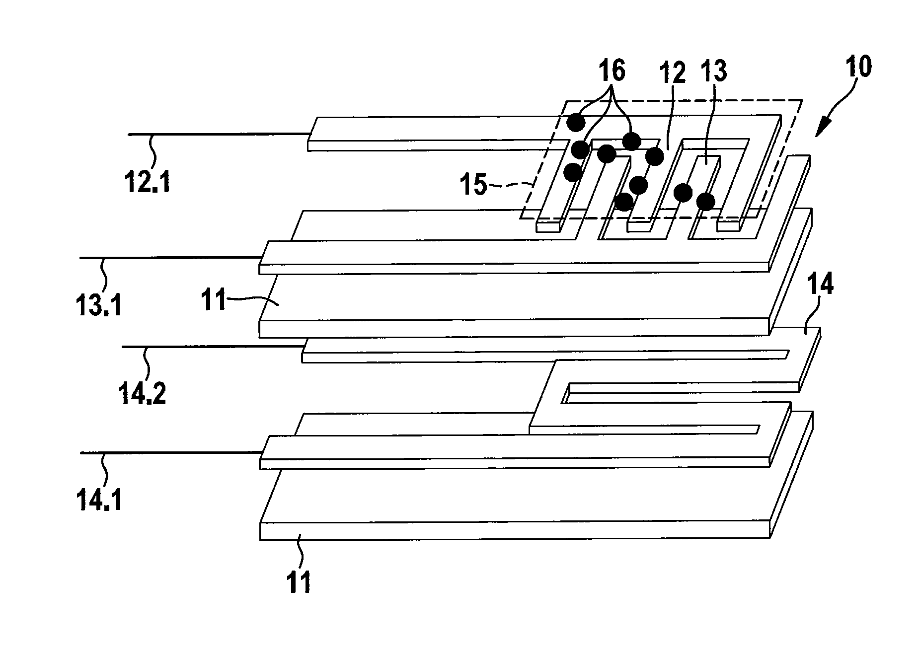
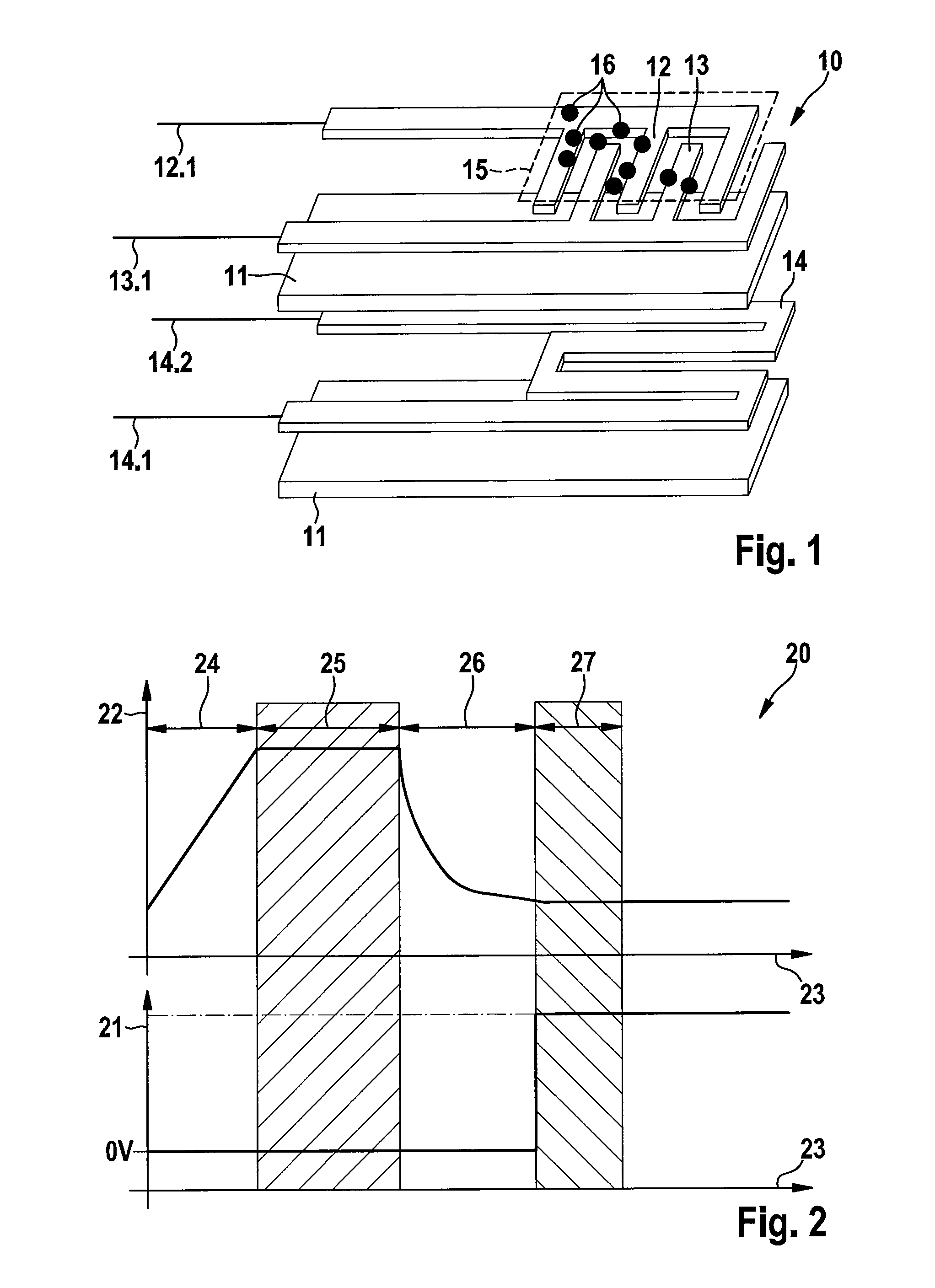
[0029]FIG. 1 is a schematic illustration of a particle sensor 10 corresponding to the prior art in an exploded illustration.

[0030]A first electrode 12 and a second electrode 13 are mounted on insulator carrier layers 11, for example made of aluminum oxide. The electrodes 12, 13 are embodied in the form of two inter-digital comb electrodes which are engaged one in the other. A first connection 12.1 and a second connection 13.1, via which the electrodes 12, 13 can be connected to a sensor control unit (not illustrated) in order to supply voltage and to carry out the measurement, are provided at the ends of the electrodes 12, 13.

[0031]In addition, in the example shown a heating element 14, which is connected to the sensor control unit via the connections 14.1, 14.2, is integrated between the insulating carrier layers 11.

[0032]If such a particle sensor 10 is operated in a particle-conducting gas stream, for example in an exhaust gas duct of a diesel engine, the particles from the gas st...


PUM

PropertyMeasurementUnit
current I(IDE)aaaaaaaaaa
sensor current I(IDE)aaaaaaaaaa
temperatureaaaaaaaaaa

Abstract

A method for operating a particle sensor (10). The particle sensor (10) has at least two inter-digital electrodes (12, 13) which engage one in the other and to which a sensor voltage U(IDE) (21) is applied in order to determine loading of the particle sensor (10) with soot particles (16). A sensor current I(IDE) (31) across the electrodes (12, 13) is measured and evaluated. In order to remove the loading with soot, a heating element (14) heats the particle sensor (10) in a regeneration phase. The method characterized in that the sensor current I(IDE) (31) is determined, and a shunt diagnosis of the particle sensor (10) is carried out in accordance with the measured sensor current I(IDE) (31).

Description

BACKGROUND OF THE INVENTION[0001]The invention relates to a method for operating a particle sensor, wherein the particle sensor has, on its surface, at least two inter-digital electrodes which engage one in the other and to which a sensor voltage U(IDE) is at least temporarily applied in order to determine loading of the particle sensor with soot particles, and a sensor current I(IDE) across the electrodes is measured and evaluated, wherein, in order to remove the loading with soot, a heating element can be additionally provided, with which heating element the particle sensor is heated in a regeneration phase.[0002]The invention also relates to a corresponding device for carrying out the method according to the invention, wherein the particle sensor is connected to an engine controller or a sensor control unit, and the engine controller or the sensor control unit has devices for diagnosing the loading of the particle sensor with soot.[0003]Particle sensors are used today, for exampl...

Claims


Application Information

Patent Timeline
Patent Type & Authority Patents(United States)
IPC IPC(8): G01R27/08G01M15/00G01N37/00G01N31/00
CPCF02D2041/2058F01N2560/20F02D41/1494F02D41/1466F01N2560/05G01N15/0656G01N15/0606
Inventor DI MIRO, ARIELBAARS, ENNOGRABIS, JOHANNESHETZNECKER, ALEXANDERKLENK, MATHIASKAMP, BERNHARDROETZLER, BASTIANSCHITTENHELM, HENRIK
Owner ROBERT BOSCH GMBH
Why Eureka
Try Eureka