
System and method for operating an ignition system

a technology of an ignition system and an ignition system, which is applied in the direction of ignition safety means, machines/engines, mechanical devices, etc., can solve the problems of engine misfire or ignition in a cylinder at an undesirable time, and reducing the possibility of providing spark to a cylinder, so as to improve engine fuel economy and/or emissions, increase the discharge current, and increase the spark energy

Active Publication Date: 2017-01-26
FORD GLOBAL TECH LLC
View PDF4 Cites 8 Cited by
  • Summary
  • Abstract
  • Description
  • Claims
  • Application Information

AI Technical Summary

Benefits of technology

The patent describes a method for controlling two ignition coils in an engine using a single control signal. This method reduces the risk of misfires and combustion at the wrong time due to degraded ignition coil signals. By ignoring the pulse width of the first command, the method prevents ignition coil charging and discharging during a subsequent cycle. The approach may improve engine fuel economy and emissions control while reducing the risk of misfires.

Problems solved by technology

Further, if the first control signal or second control signal is degraded for a particular engine cycle, the engine may misfire or begin combustion in a cylinder at an undesirable time due to undesirable spark timing.
For example, if a first portion of a first ignition coil command is absent, ignition coil charging may be inhibited or not started in response to the presence of a second portion of the first ignition coil command so that the ignition coil does not discharge during a subsequent cylinder cycle at a time coil discharge is not desirable.
In particular, the approach reduces the possibility of providing spark to a cylinder at undesirable timing.

Method used


Image

  • System and method for operating an ignition system
  • System and method for operating an ignition system
  • System and method for operating an ignition system

Examples


Embodiment Construction

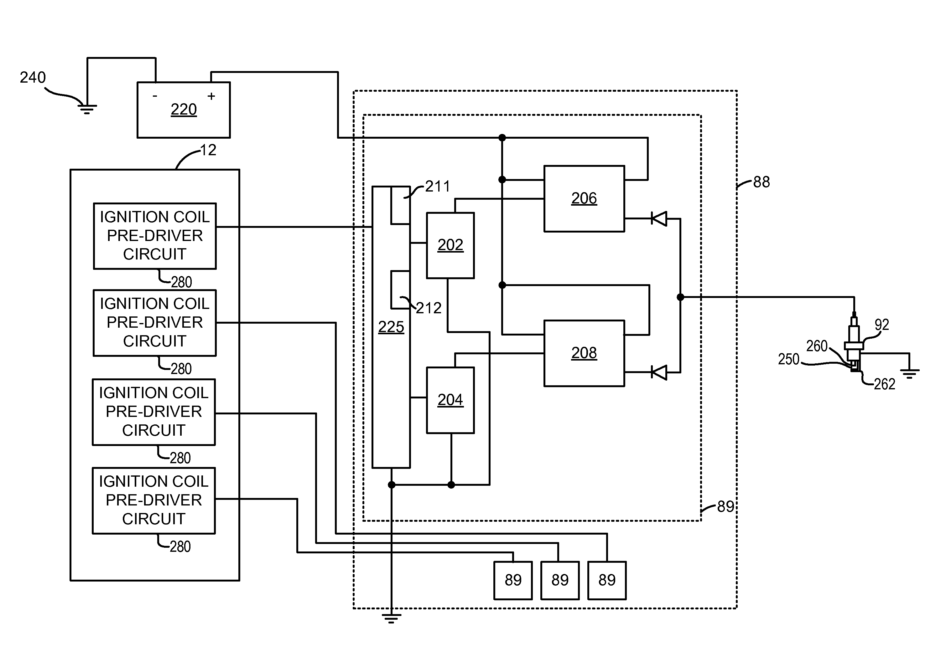
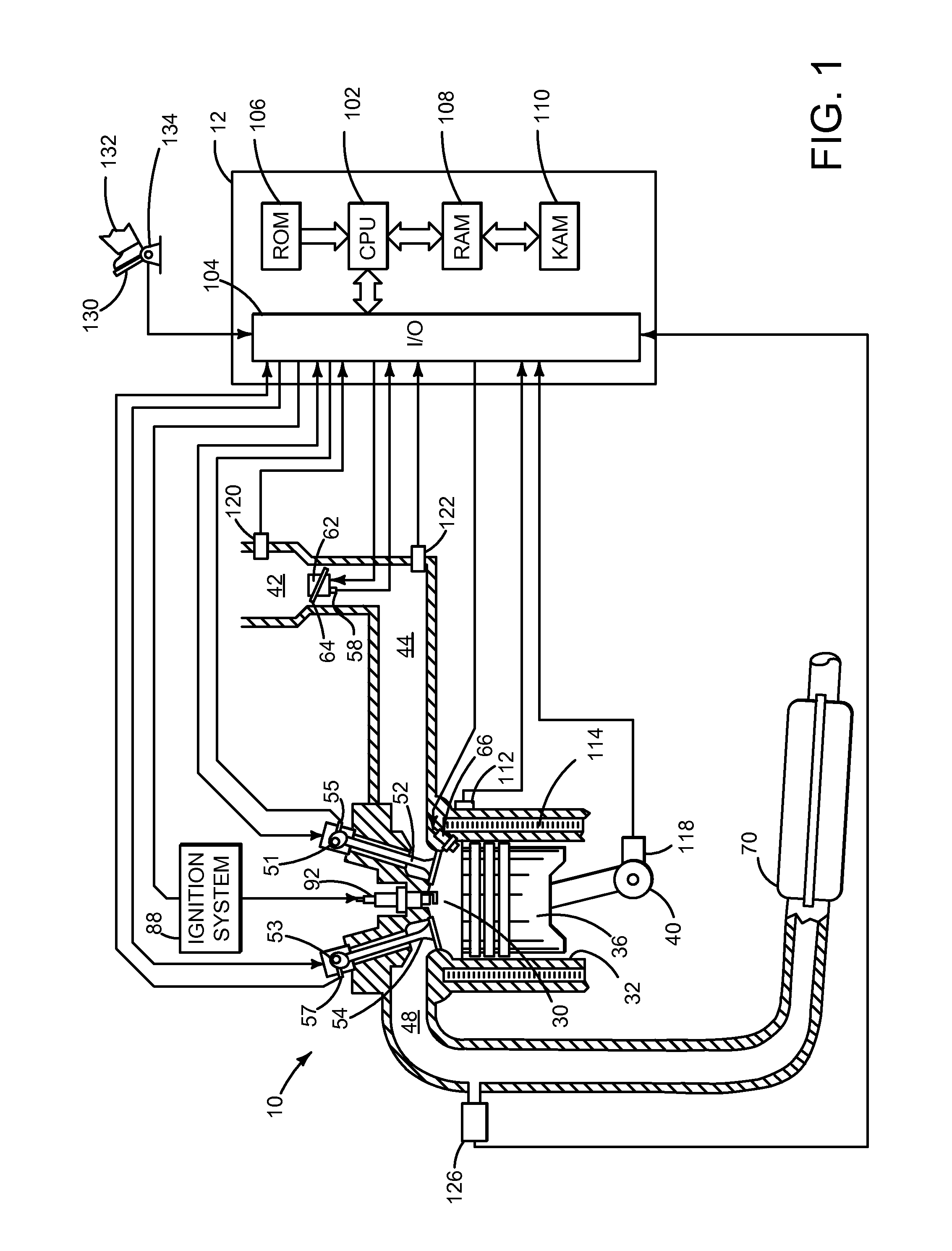
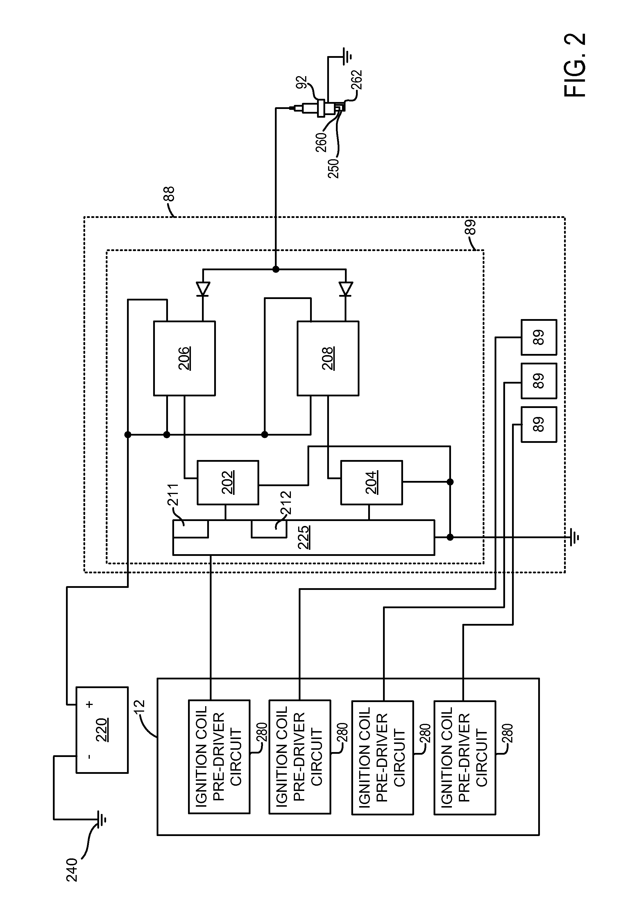
[0015]The present description is related to operating an ignition system of a spark ignited engine. In one non-limiting example, a control signal comprising a plurality of voltage pulses during a cylinder cycle is supplied to an ignition coil module via a single wire. The ignition coil module may selectively not charge and discharge an ignition coil in response to one or more missing voltage pulses. FIG. 1 shows an example engine and ignition system. FIG. 2 shows a detailed view of the ignition system shown in FIG. 1. An example ignition system control sequence is shown in FIG. 3. The possibility of improperly timed spark may be reduced as shown in the sequences of FIGS. 4-6. A method for reducing the possibility of improperly timed spark is shown in FIG. 7.

[0016]Referring to FIG. 1, internal combustion engine 10, comprising a plurality of cylinders, one cylinder of which is shown in FIG. 1, is controlled by electronic engine controller 12. Engine 10 includes combustion chamber 30 a...


PUM


Abstract

A system and method for mitigating the possibility of missing ignition coil commands is presented. In one example, one or more ignition coils may not be charged and / or discharged during a cylinder cycle in response to the absence of a voltage pulse forming at least a portion of an ignition coil command.

Description

FIELD[0001]The present description relates to a system and method for delivering spark to a spark ignited engine. The system and method may be particularly useful for engines that operate lean or with dilute mixtures.BACKGROUND AND SUMMARY[0002]A spark plug of a spark ignited engine may be supplied energy from two ignition coils. The two ignition coils may increase the spark energy and spark duration so that an engine may be operated with a lean air-fuel mixture or diluted (e.g., via exhaust gas recirculation (EGR)) to improve engine fuel economy and / or emissions. Each of the two ignition coils may be charged and discharged individually so that charging of one coil overlaps with charging of the other coil. Further, the second ignition coil may be discharged while the first ignition coil is being discharged to increase discharge current supplied to the spark plug.[0003]One way to control each of the two ignition coils is to control current supplied to the two ignition coils via two c...

Claims


Application Information

Patent Timeline
Patent Type & Authority Applications(United States)
IPC IPC(8): F02P3/05F02P9/00
CPCF02P9/002F02P3/05F02P3/02F02P9/00F02P3/0554F02P9/007F02P11/02F02P3/04
Inventor HUBERTS, GARLAN J.CZEKALA, MICHAEL DAMIANQU, QIUPING
Owner FORD GLOBAL TECH LLC
Learn More