Module substrate

a technology of modules and substrates, applied in the field of modules, can solve the problems of difficult to make power modules smaller and thinner, and achieve the effect of suppressing noise from propagation

Inactive Publication Date: 2017-01-26
TAIYO YUDEN KK
View PDF8 Cites 6 Cited by
  • Summary
  • Abstract
  • Description
  • Claims
  • Application Information

AI Technical Summary

Benefits of technology

[0022]This makes it possible to suppress noise from propagating to the periphery of the inductor.
[0023]As described

Problems solved by technology

However, because the power module disclosed in Patent Document 1 is formed from a multilayer member ha

Method used


Image

  • Module substrate
  • Module substrate
  • Module substrate

Examples


embodiment 1

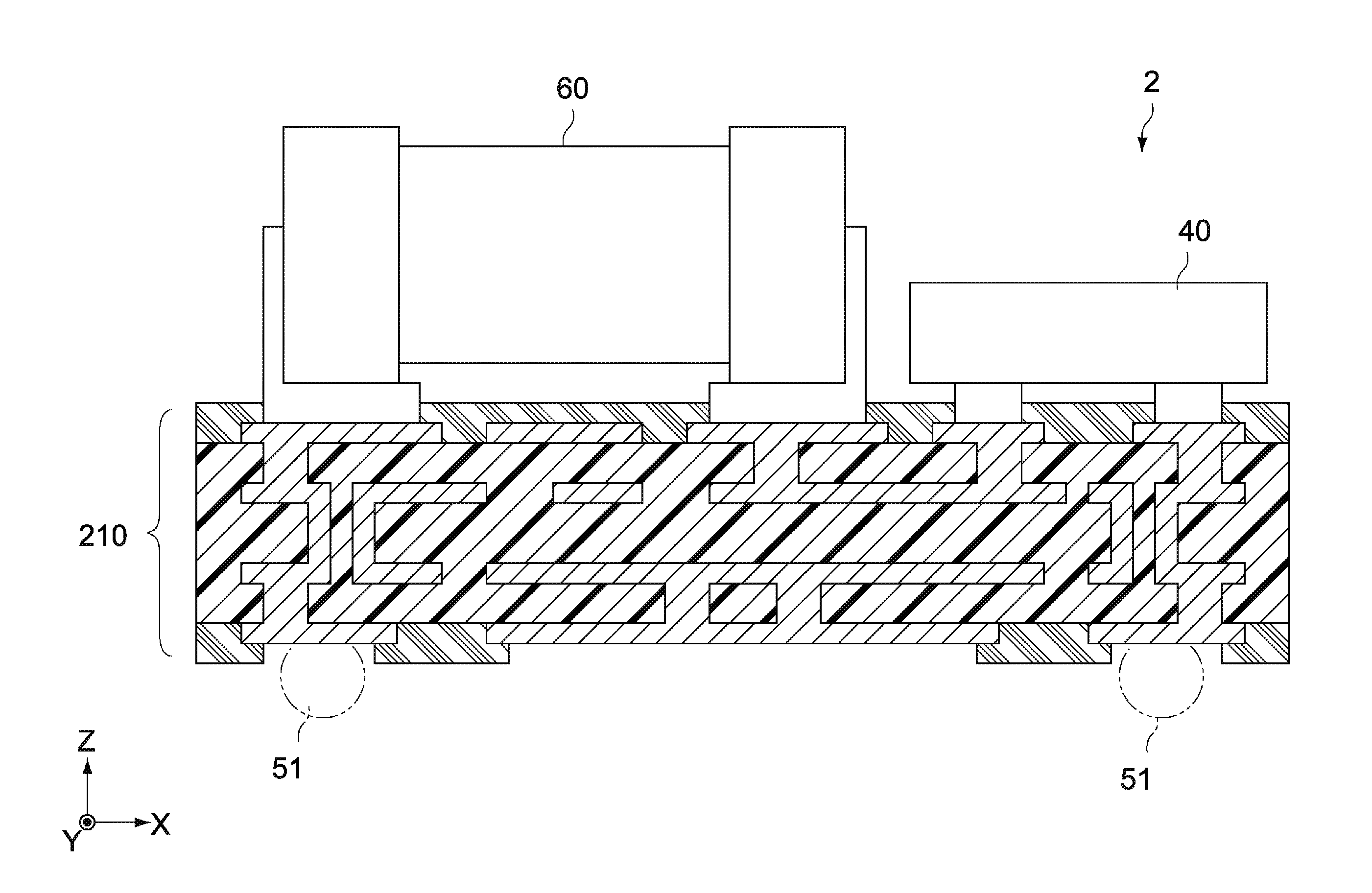
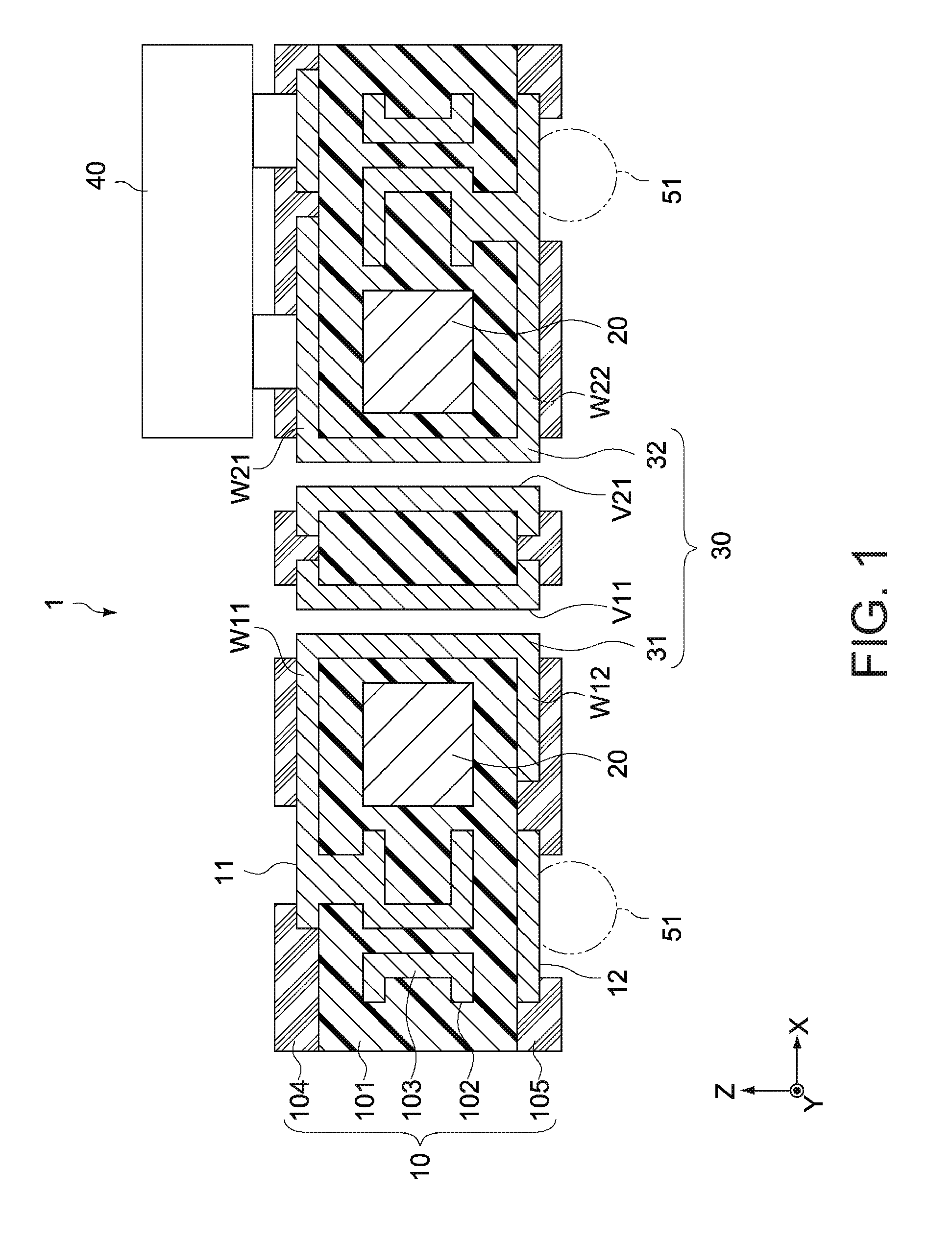
[0039]FIG. 1 is a general side cross-sectional view illustrating the configuration of a module substrate according to an embodiment of the present invention.

[0040]Note that in FIG. 1, an X axis, a Y axis, and a Z axis indicate three axial directions that are orthogonal to each other, where the X axis and the Y axis correspond to in-plane directions of the module substrate and the Z axis corresponds to a thickness direction thereof (the same applies in the other drawings as well).

[0041]

[0042]A coil component is generally a major factor making it difficult to reduce the size of a power module. Because a coil component is larger than passive components such as capacitors, resistors, and the like, even using a three-dimensional mounting technique, such as with a component-embedded substrate in which components are built into the substrate, provides only a limited size reduction effect. As such, although building a coil into a substrate using wiring can be considered, it is difficult to ...

embodiment 2

[0083]FIG. 9 is a general side cross-sectional view illustrating the configuration of a module substrate according to Embodiment 2 of the present invention, and FIGS. 10A to 13 are general cross-sectional views of primary elements, illustrating steps in a method of manufacturing that module substrate.

[0084]The following will mainly describe elements that are different from the Embodiment 1. Elements that are the same as those in the above-described embodiment will be given the same reference numerals and descriptions thereof will be omitted.

[0085]A module substrate 3 according to the present embodiment includes a substrate member 310, the magnetic core 20, and the conductor coil 30.

[0086]One surface (an upper surface, for example) of the substrate member 310 is formed as a mounting surface onto which electronic components are mounted, and another surface (a lower surface, for example) is formed as a terminal surface to which external connection terminals are connected.

[0087]The magn...


PUM


Abstract

Provided is a module substrate including an inductor that can be made thinner and smaller. A module substrate according to an aspect of the present invention includes a substrate member having a mounting surface on which electronic components are mounted, a magnetic core disposed within the substrate member, and a conductor coil provided in the substrate member and wound around the magnetic core. The module substrate has a configuration in which an inductor is built into the substrate member, which makes it possible to make the overall module substrate smaller and thinner.

Description

BACKGROUND OF THE INVENTION[0001]Technical Field[0002]The present invention relates to a module substrate, and particularly relates to a module substrate including a magnetic core and a coil wound around the magnetic core.[0003]Background Art[0004]The growth of information communication industries has led to more diverse demands with respect to electronic devices. For example, components are being mounted on main substrates at higher densities, the main substrates themselves are being made smaller and thinner, functional blocks are being modularized, and so on in order to realize devices provided with a variety of additional functions.[0005]For example, Patent Document 1 discloses a power module including a circuit substrate and an inductor. The circuit substrate has a counter surface on which electronic components such as switching transistors, a power control IC, capacitors, and the like are mounted. Meanwhile, the inductor includes a magnetic core formed from a soft magnetic meta...

Claims


Application Information

Patent Timeline
IPC IPC(8): H01F27/28H01F27/245H05K1/11H01L23/498H05K1/18
CPCH01F27/2804H05K2201/086H05K1/181H05K1/112H01F27/245H01L24/17H01L2224/16227H01L2924/15321H01L2924/19042H01L2924/19102H01L2924/19105H01L23/49827H05K2201/1003H05K2201/10522H01L23/49838H01F17/0006H01F17/062H01F2027/2814H01L23/49822H01L28/00H01L2224/16225H01L2924/14H01L2924/15311H01L2924/19041H01L2924/19043H05K1/056H05K1/165H05K3/445
Inventor SUGIYAMA, YUICHIMIYAZAKI, MASASHIHATA, YUTAKA
Owner TAIYO YUDEN KK
Why Eureka
Try Eureka