
Reconfiguration of the reactive power loop of a wind power plant

a technology of wind power plant and reactive power loop, which is applied in the direction of motors, reactive power adjustment/elimination/compensation, single network parallel feeding arrangements, etc., to achieve the effect of fast dispatching rou

Active Publication Date: 2017-01-26
VESTAS WIND SYST AS
View PDF3 Cites 31 Cited by
  • Summary
  • Abstract
  • Description
  • Claims
  • Application Information

AI Technical Summary

Benefits of technology

This patent describes a method for controlling the reactive power, voltage, or Power Factor in a wind power plant. The method allows for switching from one control mode to another, which can be beneficial for wind power plants that need fast reactive power control. The method also includes measuring an electrical variable and calculating a trigger signal based on that measurement. This enables the STATCOM to monitor the grid and detect a need for a change in control mode. Overall, this invention improves the efficiency and reliability of wind power systems by facilitating fast and effective control of reactive power.

Problems solved by technology

However, before the wind power plant can be connected to a power grid, the wind power plant has to meet the requirements of electrical performance of the wind power plant specified by grid codes.
The error signal may be caused by a change in the actual power grid voltage or a change in the external setpoint.

Method used


Image

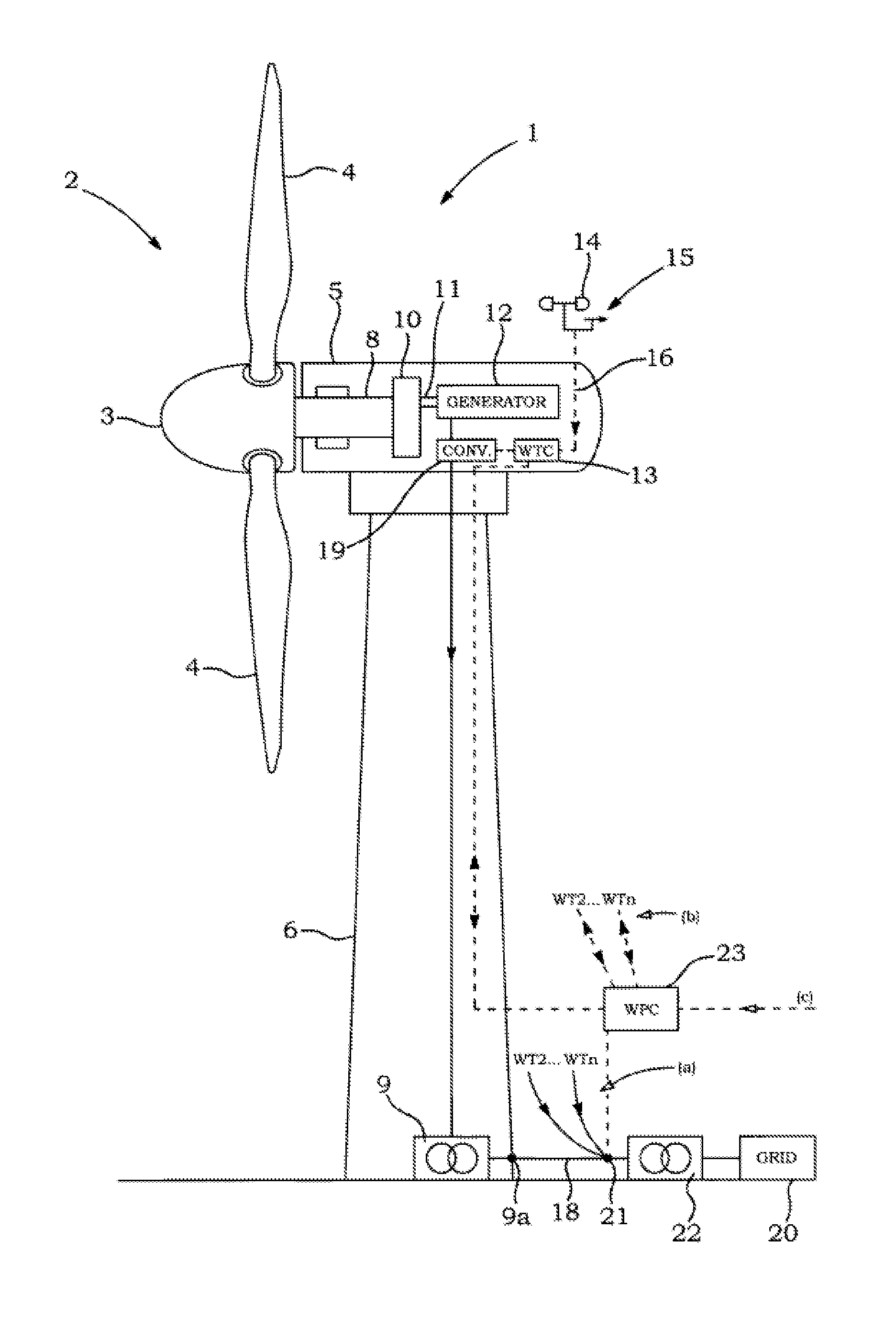
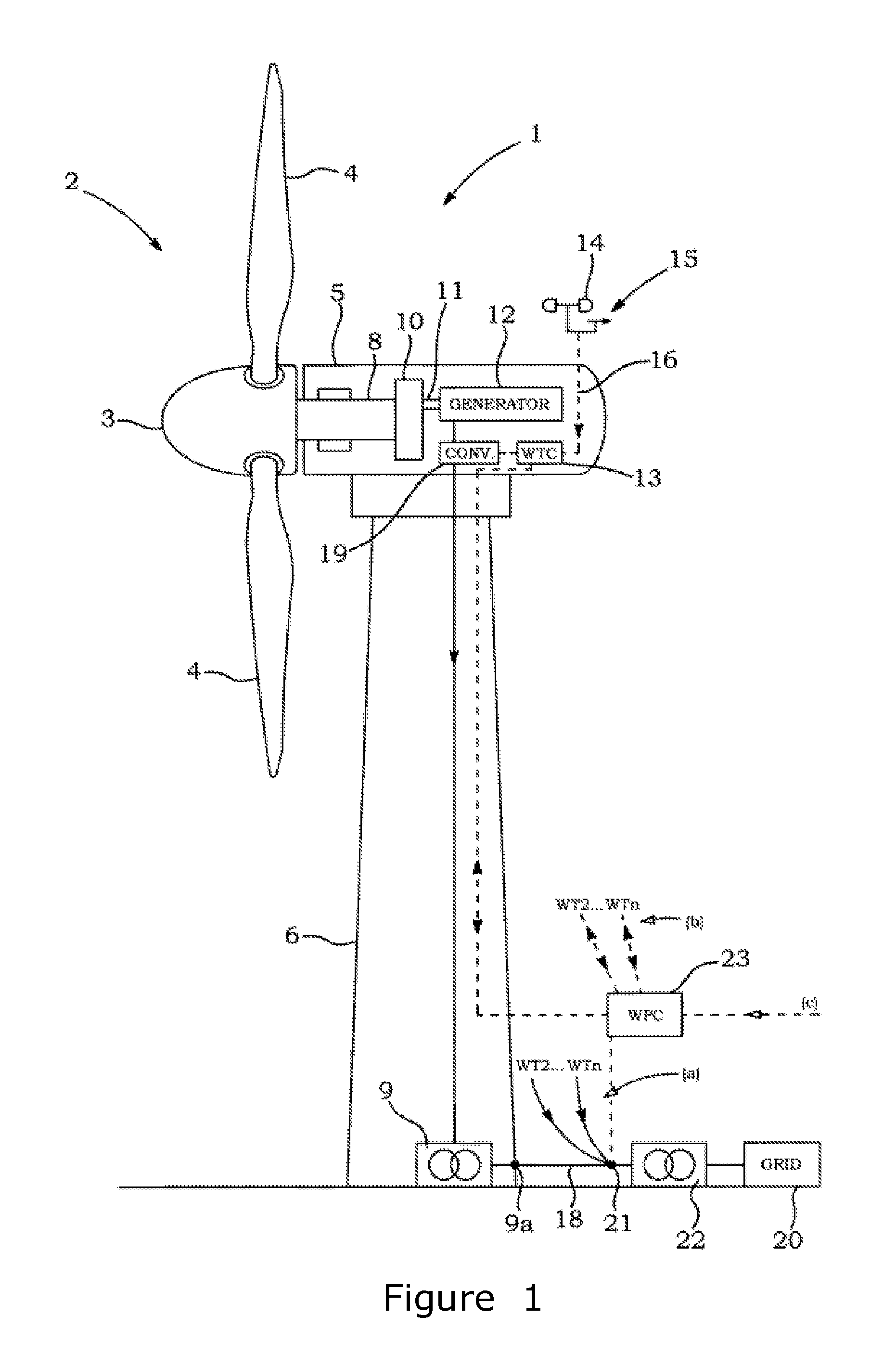
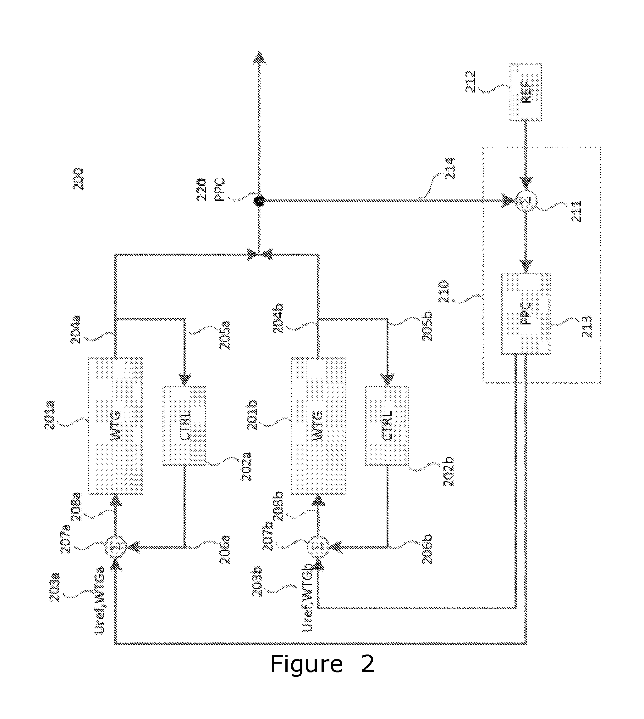
  • Reconfiguration of the reactive power loop of a wind power plant
  • Reconfiguration of the reactive power loop of a wind power plant
  • Reconfiguration of the reactive power loop of a wind power plant

Examples


Embodiment Construction

[0033]The present invention will now be explained in further details. While the invention is susceptible to various modifications and alternative forms, specific embodiments have been disclosed by way of examples. It should be understood, however, that the invention is not intended to be limited to the particular forms disclosed. Rather, the invention is to cover all modifications, equivalents, and alternatives falling within the spirit and scope of the invention as defined by the appended claims.

[0034]Typically, in some countries the master controller of the wind power plant is the power plant controller (PPC), and in other countries the STATCOM is the master controller of the wind power plant.

[0035]The idea of the present invention is that certain conditions can trigger a change dynamically between STATCOM and PPC as master of the plant.

[0036]When doing this, the power plant controller will be reconfigured accordingly.

[0037]The present invention includes, among others, a wind powe...


PUM


Abstract

The present invention relates a method of controlling a wind power plant connected to an electrical grid, the wind power plant comprises a power plant controller (350), a plurality of wind turbine generators (1) and a STATCOM (230), with a STATCOM controller, comprises: controlling the plurality of wind turbine generators in a first control mode, with the power plant controller controlling a reactive power production from each of the plurality of wind turbine generators according to a closed loop control scheme, and controlling in a first control mode with a closed loop control scheme a reactive power production from the STATCOM according to a first setpoint dispatched from the power plant controller, and controlling the reactive power production from the STATCOM in a second control mode from the STATCOM controller according to an electrical measurement in the grid, and controlling the plurality of wind turbine generators in a second control mode, with the power plant controller controlling a reactive power production from the plurality of wind turbine generators, according to a feedforward control or a close loop control, based on a second setpoint from the STATCOM controller, and switching between the first control mode and the second control mode when receiving at least one trigger signal. The invention also relates to a wind power plant according to the method.

Description

[0001]The present invention relates to a method for controlling a wind power plant connected to an electrical grid, the wind power plant comprising a power plant controller, a plurality of wind turbine generators and a STATCOM having a STATCOM controller. Further, the present invention relates to a STATCOM, and to a wind power plant of the above-mentioned sort.BACKGROUND OF THE INVENTION[0002]A wind power plant usually has a plurality of wind turbines for converting wind energy to electricity. Additionally, the wind power plant may comprise a power plant controller (PPC) and / or some sort of reactive power compensation equipment, such as static synchronous compensators (STATCOMs) or switch / switched capacitors, or others.[0003]To supply electricity to the electricity end users, the wind power plant is connected to a power grid. However, before the wind power plant can be connected to a power grid, the wind power plant has to meet the requirements of electrical performance of the wind ...

Claims


Application Information

Patent Timeline
IPC IPC(8): H02J3/38H02J3/46F03D9/25F03D7/04F03D9/00H02J3/18H02P9/14
CPCH02J3/386H02J3/1842H02J3/46F05B2270/337F03D7/048F03D9/005F03D9/25H02P9/14F03D7/0284F03D9/257H02J2300/28H02J3/381Y02E10/72Y02E10/76Y02E40/10Y02E40/20H02J3/50
Inventor GARCIA, JORGE MARTINEZROKOFYLLOS, ATHANASIOSNAYEBI, KOUROUSH
Owner VESTAS WIND SYST AS
Learn More