Method and apparatus for estimating shunt

Inactive Publication Date: 2017-02-02
MAQUET CRITICAL CARE
View PDF3 Cites 2 Cited by
  • Summary
  • Abstract
  • Description
  • Claims
  • Application Information

AI Technical Summary

Benefits of technology

The present invention provides a way to accurately estimate a person's shunt, especially the pulmonary shunt.

Problems solved by technology

There are numerous of different and often inconsistent definitions of shunt in the medical literature.
1) It is an invasive monitoring that is rarely justified even in most critically ill patients. This is because PAC is associated with potential severe complications like sepsis, pulmonary infarction, bleeding and arrhythmias among others. Besides, the use of PAC has significantly declined because its use has repeatedly failed to improve the outcome of critically ill patients.
2) The oxygen content method cannot measure CcO2 directly. This value is calculated based on the assumption that capillary blood is fully saturated. However, this assumption might not be true even if 100% inspired oxygen fraction (FiO2) were used.
3) When using a FiO2<1, this method becomes only a rough estimate of venous admixture.
However, these methods are cumbersome, costly, time-consuming and impossible to apply at the bedside and, therefore, they cannot be considered clinical monitoring methods.
Due to said shortcomings, the above mentioned methods fail to easily and reliably provide an indication of shunt in mechanically ventilated patients in operating theatres or in intensive care units.
Despite being widely used, most physicians agree that these indexes are not real substitutes of shunt in critically ill patients undergoing complex clinical processes.
The estimations discussed in these publications are gross calculations based on simplistic and, many times unrealistic assumptions and, therefore, their clinical use is questionable.
However, calculating shunt from O2-related parameters has been proved difficult and uncertain since this requires several assumptions to be made regarding unknown physiological parameters, as will be discussed in more detail in the specification following hereinafter.

Method used


Image

  • Method and apparatus for estimating shunt
  • Method and apparatus for estimating shunt
  • Method and apparatus for estimating shunt

Examples


Embodiment Construction

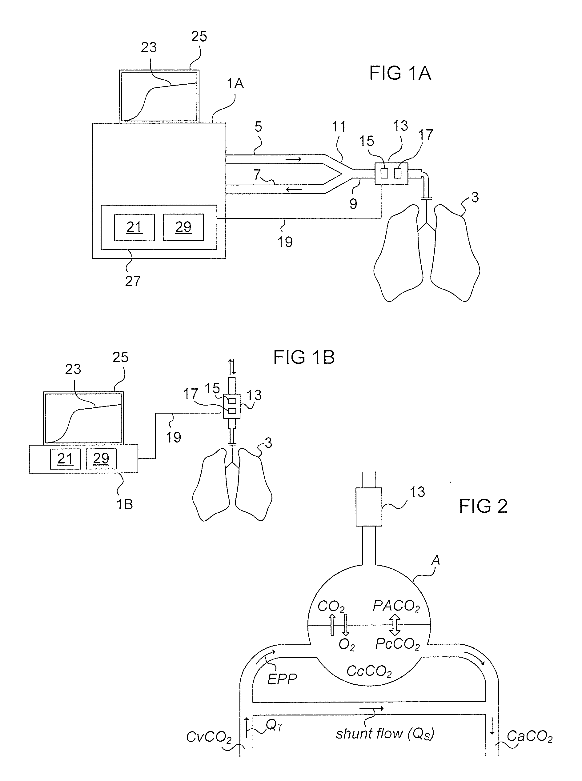
[0087]FIG. 1A illustrates an apparatus 1A according to an exemplary embodiment of the invention. In this embodiment the apparatus is a ventilator for providing ventilatory treatment to a patient 3 connected to the ventilator. The ventilator is connected to the patient 3 via an inspiratory line 5 for supplying breathing gas to the patient 3, and an expiratory line 7 for conveying expiration gas away from the patient 3. The inspiratory line 5 and the expiratory line 7 are connected to a common line 9, via a so called Y-piece 11, which common line is connected to the patient 3 via a patient connector, such as an endotracheal tube.

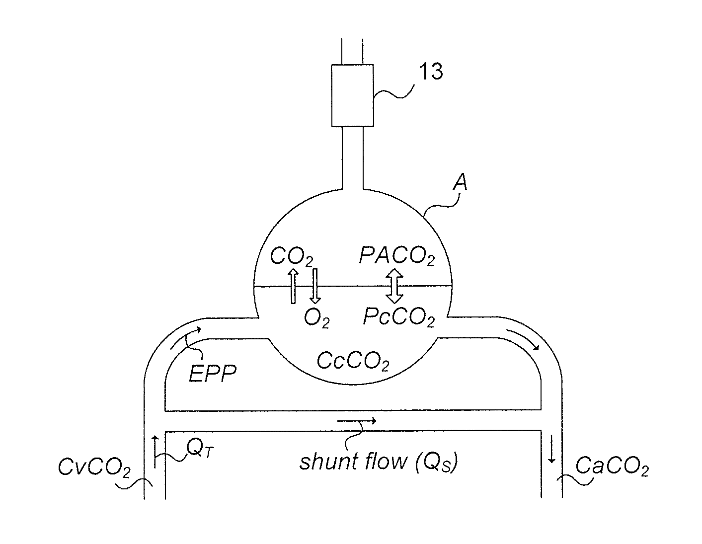
[0088]A capnograph 13 configured for volumetric capnography measurements is arranged in the proximity of the airways opening of the patient 3. In this exemplary embodiment, the capnograph 13 is arranged in the common line 9 and exposed to all gas expired and inspired by the patient 3. The capnograph 13 comprises a flow or volume sensor 15 for measuring at leas...


PUM


Abstract

In a CO2-based method for estimating shunt of a subject, a first value related to alveolar CO2 of the subject is obtained from CO2 measurements on expiration gas exhaled by said subject, a second value is obtained related to arterial CO2 of the subject, a third value is obtained related to cardiac output [QT] or effective pulmonary perfusion [EPP] of the subject, a fourth value is obtained related to CO2 elimination [VCO2] of the subject, the shunt of the subject is calculated based on said first, second, third and fourth values. The method allows the shunt of the subject to be determined in a non-invasive or minimally-invasive way without requiring determination of the venous or capillary CO2 contents of the subject, which in turn allows the method to be carried out at the bedside, enabling reliable monitoring of shunt in clinical practice.

Description

BACKGROUND OF THE INVENTION[0001]Field of the Invention[0002]The present invention relates to a method, an apparatus and a computer program for estimating shunt, and in particular to a method, apparatus and computer program for minimally invasive estimation of shunt based on carbon dioxide measurements.[0003]Description of the Prior Art[0004]Human cells need oxygen (O2) to live because they obtain energy by consuming O2 and glucose throughout aerobic metabolism. The lungs take O2 molecules from air during breathing, which diffuse into capillary blood through the alveolar-capillary membrane—a passive process called gas exchange. O2 molecules then bind to hemoglobin and are transported by the blood assuring an optimal O2 delivery to all body cells.[0005]Gas exchange at the lung level is the key process and it depends on the close matching of ventilation delivering O2 to the gas exchange surface, the alveolar-capillary membrane, and blood perfusion taking up oxygen and offloading carbo...

Claims


Application Information

Patent Timeline
IPC IPC(8): A61B5/0205A61B5/00A61B5/097
CPCA61B5/0205A61B5/097A61B5/14552A61B5/0836A61B5/742
Inventor SUAREZ SIPMANN, FERNANDOTUSMAN, GERARDOBOHM, STEPHANSANTOS OVIEDO, ARNOLDO
Owner MAQUET CRITICAL CARE
Why Eureka
Try Eureka