Linear motion mechanism formed integrally

a motion mechanism and integral technology, applied in the direction of machine supports, manufacturing tools, gearing, etc., can solve the problems of complex assembly process and adjustment operations, weak structural strength, and inability to adjust, etc., to achieve easy reduction in weight and size, simple production, and structural robustness.

Active Publication Date: 2017-02-02
NEC CORP
View PDF1 Cites 1 Cited by
  • Summary
  • Abstract
  • Description
  • Claims
  • Application Information

AI Technical Summary

Benefits of technology

[0007]An object of the present invention is to provide a novel linear motion mechanism with precise linear motion, which has structural robustness and allows easy reduction in weight and size, simple production and easy operation.

Problems solved by technology

However, the above-mentioned linear motion actuator using reduction gearing mechanism requires a plurality of parts, complicated assembly process and complicated adjustment operations.
The above-mentioned linear motion mechanism using the elasticity of combined elastic plates has the spatial arrangement of a plurality of elastic plates, resulting in weakness in structural strength, which makes it difficult to achieve precise displacements.
Accordingly, the existing techniques cannot achieve a light-weight, miniaturized and simply-manufactured linear motion mechanism providing high precision.

Method used


Image

  • Linear motion mechanism formed integrally
  • Linear motion mechanism formed integrally
  • Linear motion mechanism formed integrally

Examples


first exemplary embodiment

1. First Exemplary Embodiment

1.1) Structure

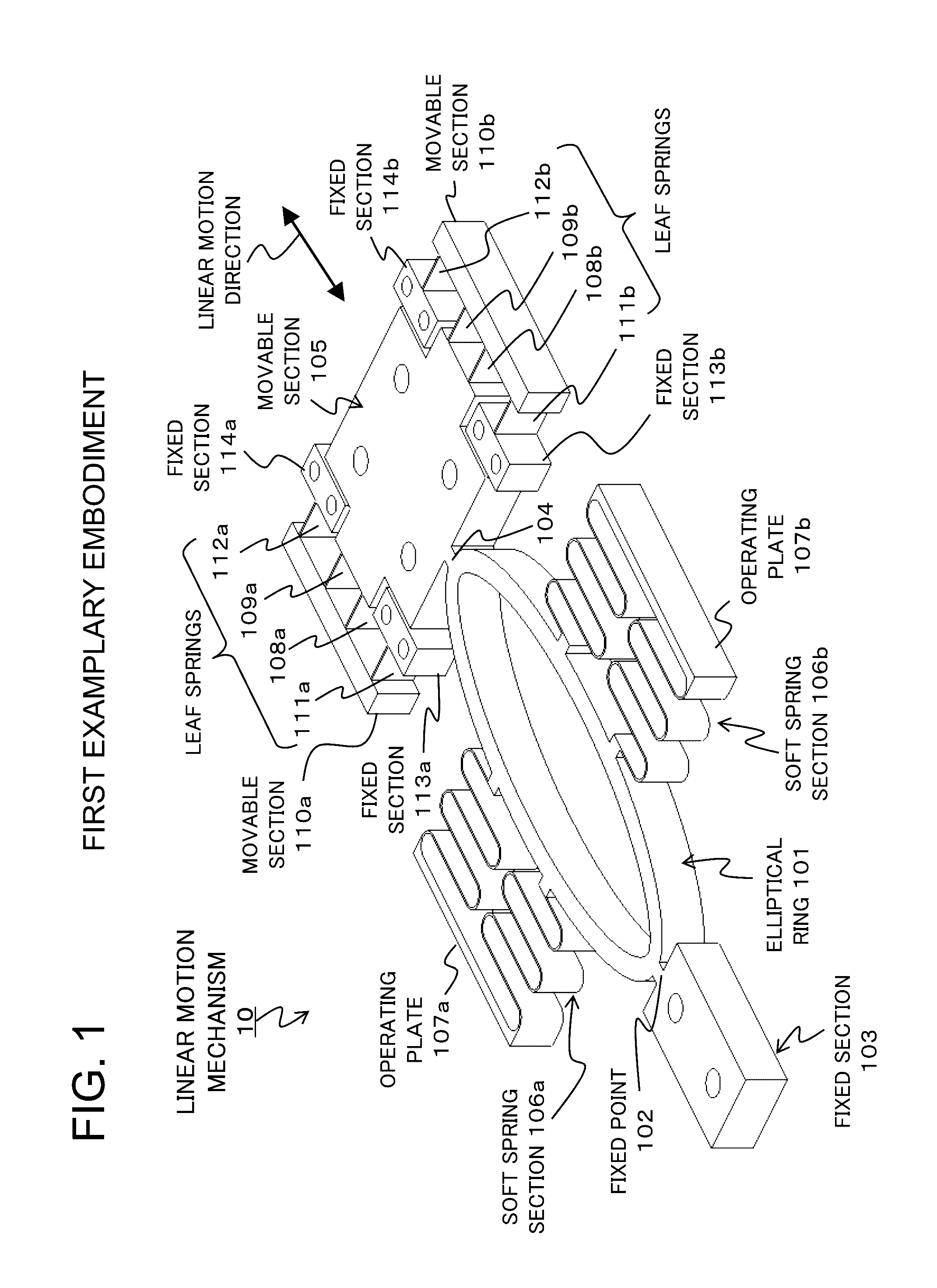
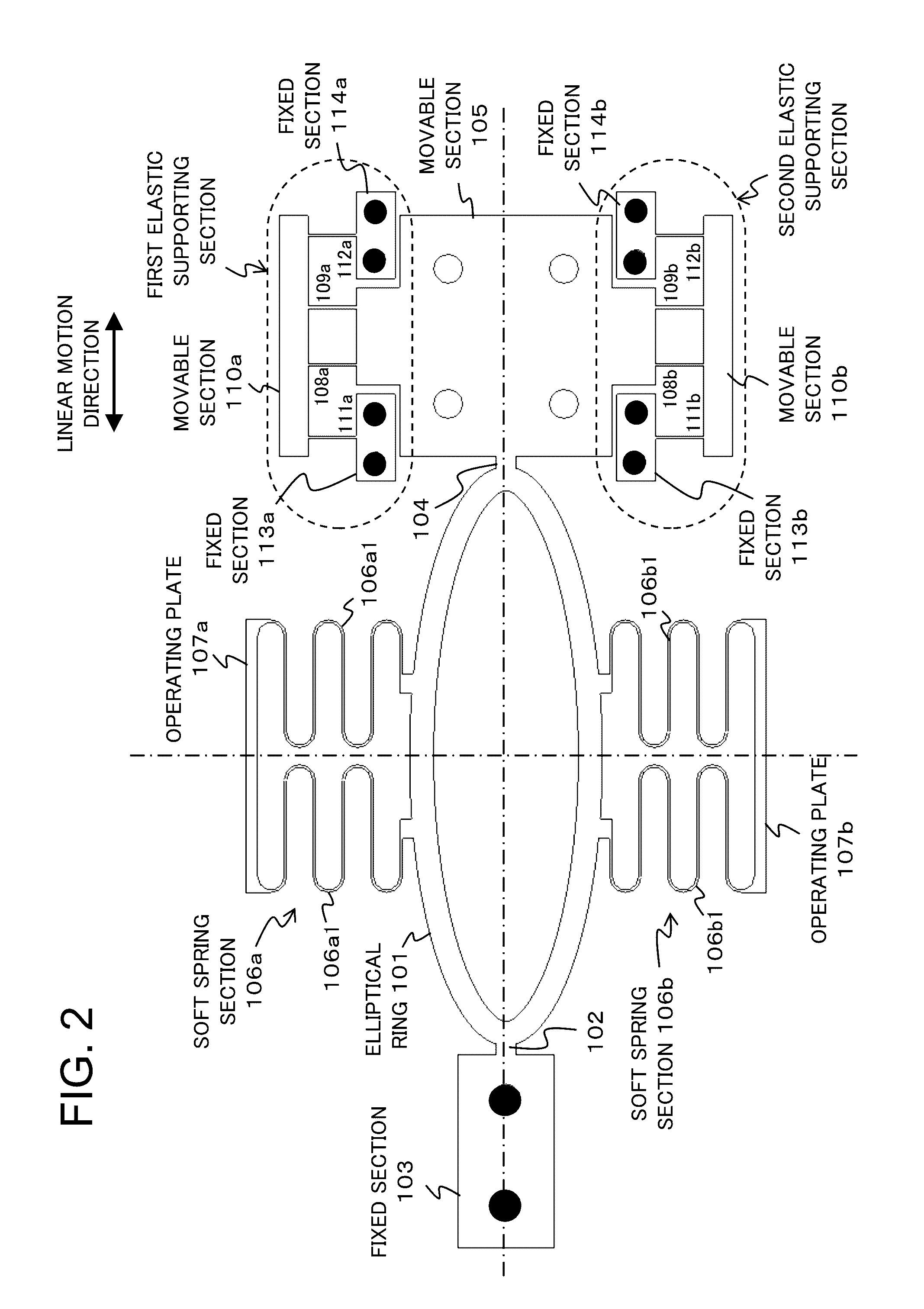
[0036]Referring to FIGS. 1 and 2, a linear motion mechanism 10 according to the first exemplary embodiment includes an elliptical ring 101 having a fixed point 102 connected to a fixed section 103 and a movable point 104 connected to a movable section 105. The fixed point 102 and the movable point 104 are both ends of the major axis of the elliptical ring 101.

[0037]The elliptical ring 101 has soft spring sections 106a and 106b which are fixed respectively to both sides of the elliptical ring 101 in the direction of the minor axis so that the elliptical ring 101 is sandwiched between the soft spring sections 106a and 106b. The respective ends of the soft spring sections 106a and 106b are provided with operating plates 107a and 107b. Preferably, the soft spring sections 106a and 106b have the same spring constant so as to press or stretch the elliptical ring 101 equally. In FIG. 1, the soft spring sections 106a and 106b are a bellows-like spr...

second exemplary embodiment

2. Second Exemplary Embodiment

2.1) Structure

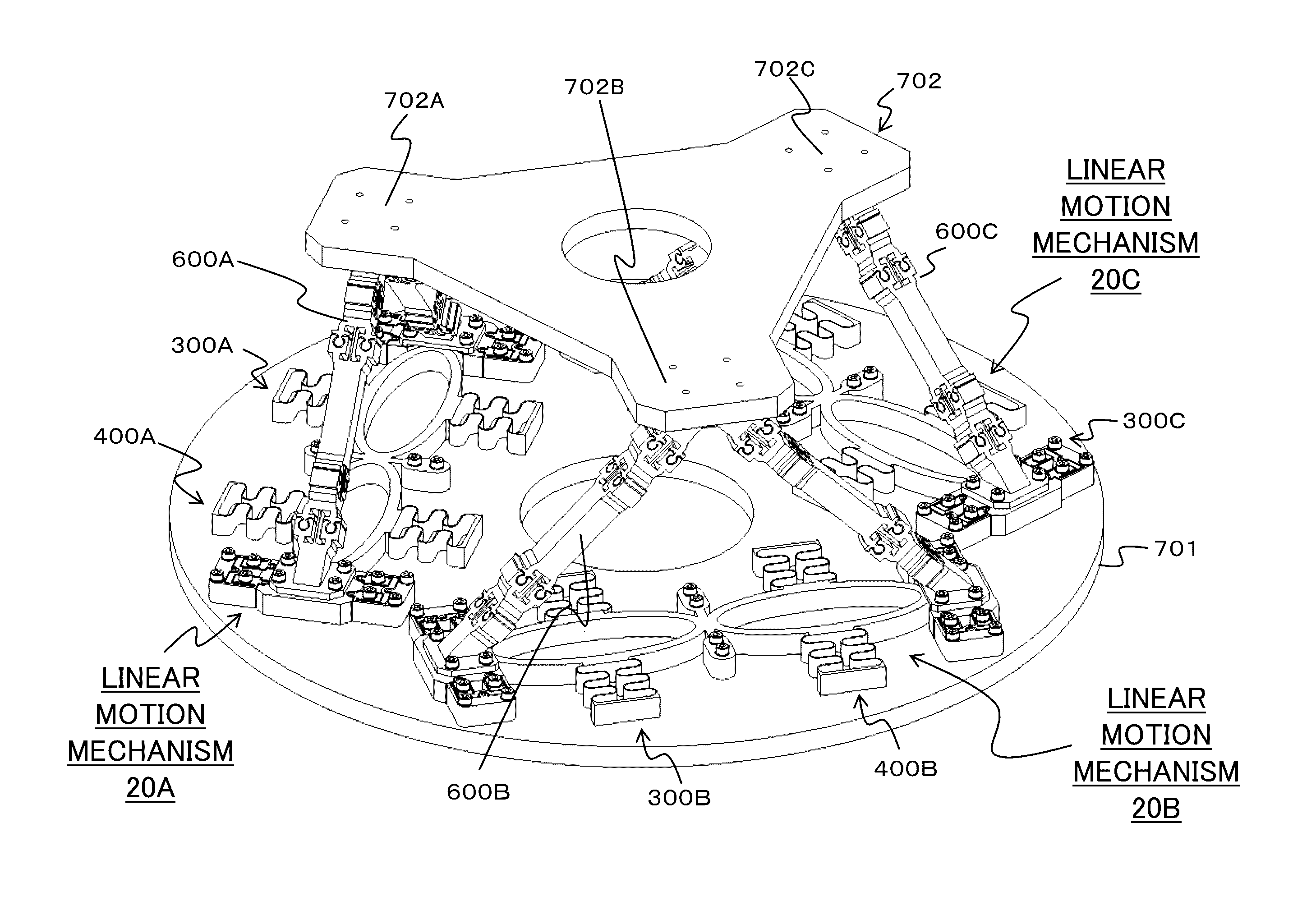
[0049]As shown in FIGS. 5 and 6, a linear motion mechanism 20 according to the second exemplary embodiment is formed by a combination of first linear motion section 300 and second linear motion section 400, each of which has the substantially same functional structure as the linear motion mechanism 10 as shown in FIGS. 1 and 2. The first linear motion section 300 and the second linear motion section 400 are arranged such that the major axes of the elliptical rings 301 and 401 are in alignment with each other. The first linear motion section 300 and the second linear motion section 400 have a common fixed section 303 / 403 corresponding to the fixed section 103 of the first exemplary embodiment. Accordingly, the linear motion mechanism 20 provides movable sections 305 and 405 respectively on its both sides.

[0050]More specifically, the first linear motion section 300 includes an elliptical ring 301 having a fixed point 302 connected to a fixed...


PUM


Abstract

A linear motion mechanism with precise linear motion has structural robustness and allows easy reduction in weight and size, simple production and easy operation. The linear motion mechanism includes: an elastic arrangement which is arranged to transform an input direction and an input displacement to an output direction and an output displacement, wherein the output direction is orthogonal to the input direction; an operating member which is arranged to deform the elastic arrangement in the input direction by the input displacement; and a movable member fixed to the elastic arrangement to move in the output direction by the output displacement.

Description

BACKGROUND OF THE INVENTION[0001]1. Field of the Invention[0002]The present invention relates to a linear motion mechanism which uses the elasticity of springs.[0003]2. Description of the Related Art[0004]With the increasing market demand for precision technology, a linear motion actuator providing high precision has become important for machinery requiring precise displacement such as multiple-degree-of-freedom displacement mechanism, micro-manipulator or the like. In most cases, such a fine linear motion actuator employs reduction gearing mechanism, which requires not only a plurality of parts such as different gears but also backlash adjustment of gears and other alignments during its assembly.[0005]In order to eliminate the need of backlash adjustment and other alignments, there has been proposed a simplified linear motion mechanism using a combination of elastic plates to allow fine linear displacement (see Japanese Patent Unexamined Publication No. JP2003-075572). More specifi...

Claims


Application Information

Patent Timeline
Patent Type & Authority Applications(United States)
IPC IPC(8): F16H25/18
CPCF16H25/183B25J7/00F16H21/44B25J9/0042F16M11/121F16M11/18B23Q1/34B23Q1/36B25J9/0051B81B3/00F16F1/00
Inventor KUROSE, MINORUHAMADA, KAZUOKATSUYAMA, YOSHIHIKOKAMIZONO, TAKASHIKOBAYASHI, TAKUROTANIMICHI, NAOTOHAPPY, TSUI
Owner NEC CORP
Why Eureka
Try Eureka