Pneumatic tire

a technology of pneumatic tires and bead parts, which is applied in the field of pneumatic tires, can solve the problems of reducing the durability of the bead portion, and achieve the effects of reducing stress concentration, suppressing the heat generation of the bead portion, and reducing the volume of the inner apex rubber having difficulty in heat dissipation

Active Publication Date: 2017-02-09
SUMITOMO RUBBER IND LTD
View PDF13 Cites 2 Cited by
  • Summary
  • Abstract
  • Description
  • Claims
  • Application Information

AI Technical Summary

Benefits of technology

[0023]The pneumatic tire according to the present invention includes a bead core including an axially inner core and an axially outer core respectively disposed on an axially inner side and the axially outer side of the carcass ply, and an inner bead apex rubber and an outer bead apex rubber extending radially outward from the inner core and the outer core in a tapered shape, respectively. Since an outer apex height Ho is in a range of from 120% to 150% of an inner apex height Hi, an outer end of the inner bead apex rubber and an outer end of the outer

Problems solved by technology

Such stress concentration causes decre

Method used


Image

  • Pneumatic tire
  • Pneumatic tire
  • Pneumatic tire

Examples


first embodiment

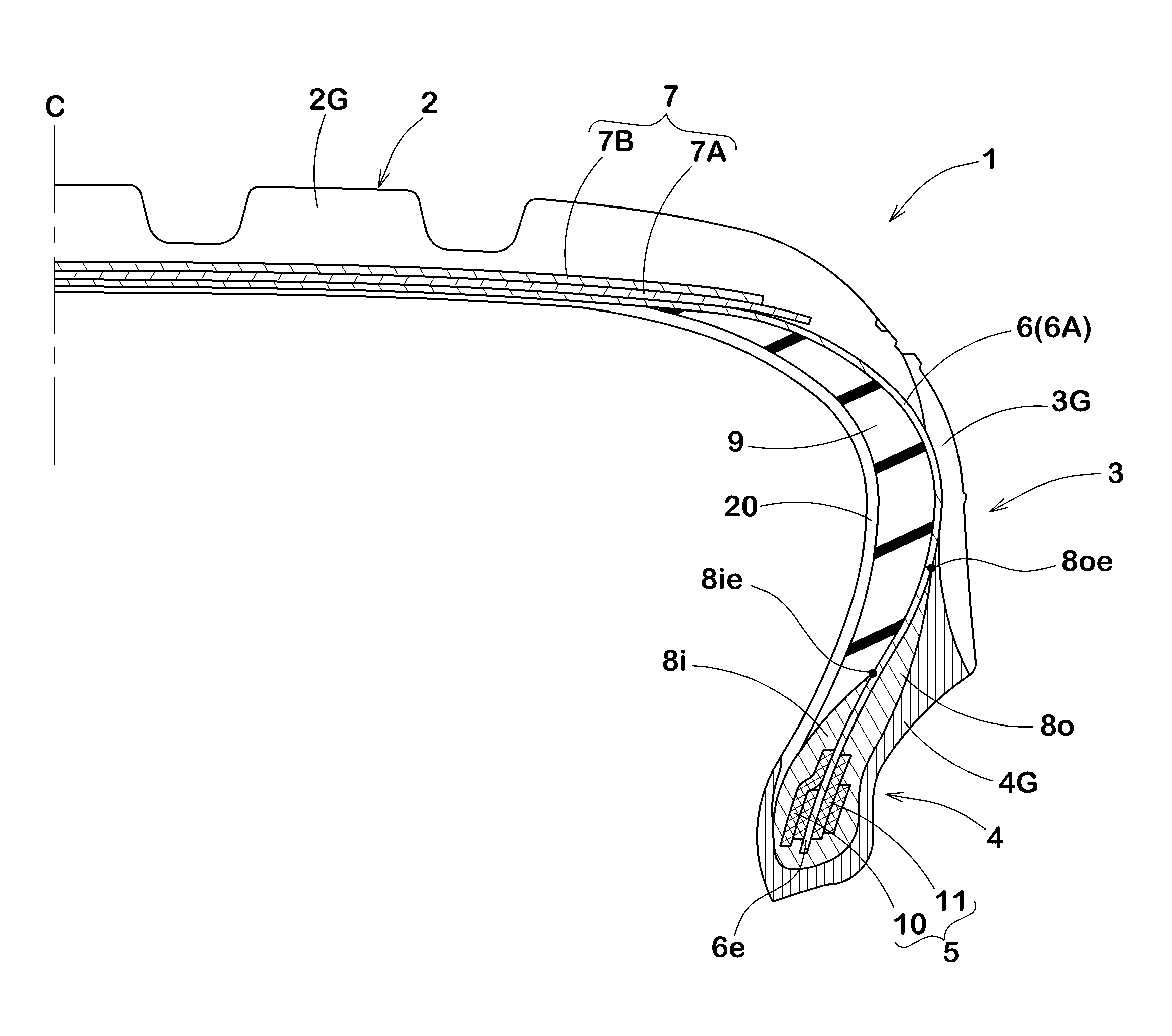
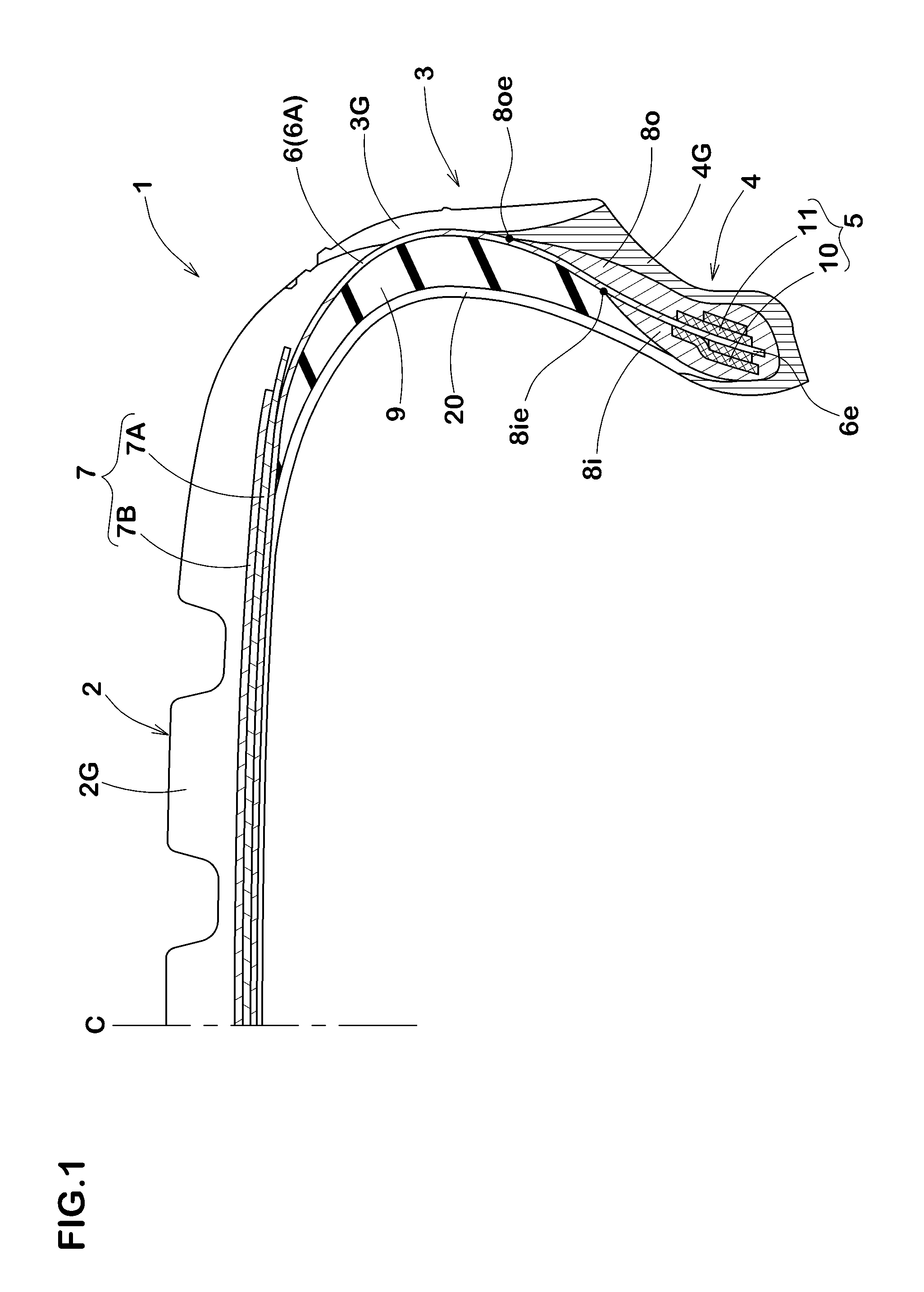
[0031]FIG. 1 is a cross-sectional view of a right half of a pneumatic tire 1 (hereinafter, simply referred to as “tire”) according to the present embodiment. The pneumatic tire 1 includes a tread portion 2, a pair of sidewall portions 3, a pair of bead portions 4 with a respective one of bead cores 5, a carcass 6 and a belt layer 7 disposed radially outside the carcass 6. In this embodiment, the pneumatic tire 1 is shown as a passenger car tire.

[0032]The pneumatic tire 1 illustrates in FIG. 1 is under a standard state in which the tire is mounted on a standard wheel rim (not illustrated) and is inflated to a standard internal pressure, but is loaded with no load.

[0033]The “standard wheel rim” is a wheel rim approved for each tire by standard organizations on which the tire is based. For example, the standard is a standard rim in the case of JATMA, a “Design Rim” in the case of TRA, and a “Measuring Rim” in the case of ETRTO. Also the “standard internal pressure” means an air pressur...

example

First Embodiment

[0083]A pneumatic tire of size 245 / 45R18 having a basic structure shown in FIG. 1 was made based on specifications shown in Table 1. A durability of a bead portion and a run-flat durability were tested.

Durability of Bead Portion

[0084]Each test tire was assembled on a rim 18×8.0 J was run on a test drum having a diameter 1.7 m while applying a large load to the bead portion under conditions of an internal pressure 360 kPa, a load 13.12 kN, a speed of 80 km / h. A mileage was measured until the bead portion was damaged. The test result was indicated by an index that the mileage of Example 1 being 100. The larger the value is, the higher and better the durability of the bead portion is.

Run-Flat Durability

[0085]Each test tire was assembled on a rim 18×8.0 J was run on a test drum having a diameter 1.7 m under conditions of an internal pressure 0 kPa, a load 4.53 kN, a speed of 80 km / h. A mileage was measured until the tire sounded an abnormal noise. The test result was ind...

second embodiment

[0087]A tire of (size: 245 / 45RF18 96Y) having a basic structure shown in FIG. 3 was made based on the specifications shown in Table 2. Its performance was tested.

[0088]A test method is as follows.

Rim-Off Resistance

[0089]Each test tire was assembled on a rim (8.0×18) without a valve core and mounted on one of front wheels of a test vehicle in a punctured state having an internal pressure of zero (gauge pressure). The vehicle was run on a wet road surface with water film while keeping a handle was fully locked. After running at a speed of 30 km / h, a rim-off of the tire was visually confirmed. After repeating the above-mentioned test six times per test tire, evaluations were conducted by a ten-point method based on the number of times that the rim-off were confirmed. The larger the value is, the better the rim-off resistance is.

TABLE 2Ref.Ref.Ex. 1Ex. 2Ex. 1Ex. 2Ex. 3Ex. 4Ex. 5Ex. 6Ex. 7Ex. 8Number of turns of inner9121216121612121212core (times)Number of turns of first1446464444inner ...


PUM


Abstract

A pneumatic tire comprises a carcass formed of a carcass ply extending between a pair of bead portions in a toroidal shape, and a bead core disposed in a respective one of the bead portions, the bead core comprising an axially inner core and an axially outer core respectively disposed on an axially inner side and the axially outer side of the carcass ply. The bead portion comprises an inner bead apex rubber extending radially outward from the inner core, and an outer bead apex rubber extending radially outward from the outer core. An outer apex height Ho from a bead base line to a outer end of the outer bead apex rubber is in a range of from 120% to 150% of an inner apex height Hi from the bead base line to the outer end of the inner bead apex rubber.

Description

TECHNICAL FIELD[0001]The present invention relates to a pneumatic tire having an excellent durability of a bead portion.BACKGROUND ART[0002]Patent Document 1 discloses a pneumatic tire including a carcass formed of a carcass ply extending between a pair of bead portions in a toroidal shape, and a bead core disposed in a respective one of the bead portions and comprising an axially inner core and an axially outer core respectively disposed on an axially inner side and an axially outer side of the carcass ply. In the pneumatic tire, an inner bead apex rubber is disposed radially outward of the inner core, and an outer bead apex rubber is disposed radially outward of the outer core.RELATED ART DOCUMENTSPatent Documents[0003]Patent Document 1: Japanese unexamined Patent Application Publication No. 2012-126299[0004]In the above-mentioned pneumatic tire, an outer end of the inner bead apex rubber and an outer end of the outer bead apex rubber are at closely. Therefore, in the vicinity of ...

Claims


Application Information

Patent Timeline
IPC IPC(8): B60C15/06B60C15/05
CPCB60C15/0603B60C15/05B60C2015/046B60C2015/061B60C2015/0696B60C2015/0614B60C15/0018B60C17/0009B60C15/0607B60C2017/0072B60C15/06
Inventor KUJIME, TOMOYUKI
Owner SUMITOMO RUBBER IND LTD
Why Eureka
Try Eureka