Illuminated trim fitting

a technology of illumination and fittings, applied in the direction of fixed installation, transportation and packaging, light and heating equipment, etc., can solve the problems of not being able to identify the outside of the cover fitting or sealing strip as an illuminated fitting, comparatively complex structure, and high manufacturing cost. , to achieve the effect of constant light gap width

Active Publication Date: 2017-02-09
PLASMAN US HOLDCO LLC
View PDF1 Cites 7 Cited by
  • Summary
  • Abstract
  • Description
  • Claims
  • Application Information

AI Technical Summary

Benefits of technology

[0016]The lighting structure may be formed by a luminescent film, in particular an OLED film (organic light emitting diode), wherein a PHOLED (phosphorescent OLED) is also considered to be covered by the term OLED. An OLED is appropriate because it is of extremely flat design, requires only a very small installation space and can be printed or bonded onto virtually any material. During their manufacture, OLEDs provide a significant cost saving over LCD technology, in particular because the OLEDs can be easily processed and are simple to actuate. Compared to LEDs, OLEDs generate less heat and have a larger temperature range. The low operating voltage which is required for OLEDs is also advantageous. Furthermore, the use of OLEDs ensures that in the illuminated state the trim fitting does not experience any critical heating caused by the illumination. However, use is not necessarily restricted to OLEDs as a lighting structure. In particular, other film-like lighting structure, for example an electroluminescent film (LM film) are also possible as further lighting structure. The lighting structure can be configured, in particular, as a lighting strip which extends along the trim fitting. The thickness of such a luminescent film or of such a luminescent film strip may be less than a millimeter, in particular approximately 0.2 mm to 0.3 mm.
[0020]In order to keep the width of the light gap constant over the entire strip length of the typically thin-walled, and therefore per se flexible, profiled strip, a spacer element which is arranged between the profiled strip and the vehicle outer surface can be provided, on which spacer element the profiled strip is at least indirectly supported. As a result, the light gap width can be defined, and there is no risk of the light gap width varying over the length of the strip owing to fabrication inaccuracies or other material distortion. Such a spacer element can be formed, in particular, by a limb of the sealing strip which rests directly on the vehicle outer skin and on which the profiled strip is arranged. However, a spacer element which is separate from the sealing strip can also be provided, on which spacer element, in particular, the functional limb, bearing the lighting structure, of the profiled strip cross section is supported directly or indirectly via the lighting structure. This spacer element can also be fabricated from a transparent material, with the result that, in particular, when the lighting structure itself is supported on this spacer element, the emitted light is directed through the spacer element to the light gap.

Problems solved by technology

However, the structure is comparatively complex and costly to manufacture and furthermore does not permit any continuously uniform illumination over the entire length of the fitting because of the LEDs which are provided only at discrete positions.
Furthermore, it is considered disadvantageous that the cover fitting or sealing strip can be identified from the outside as an illuminated fitting owing to its external design.
The illumination module permits only a restricted illumination range, and the design of the trim fitting is complex as a result of the need for fitting a cut out into the trim strip.
An additional factor here is also that this type of design of a trim fitting compromises the high-quality visual effect because the visible surface of the trim fitting is penetrated.
In this context, the light elements are embedded at least partially in the plastic moulded mass of a visible part, which considerably complicates the manufacture of the plastic component.
Furthermore, the trim fitting has to be fabricated from plastics which can be through-lit, which can give a less high-quality impression compared to other materials.
The last-mentioned disadvantage of the restricted material selection also relates to the illuminated trim fittings which are disclosed in documents EP 2 556 996 A2 and EP 2 363 324 A1.
This design is relatively complex and requires additional components and does not permit any fittings which are very flat and narrow in design.
Document DE 201 10 352 U1 describes a completely comparable and therefore also similarly disadvantageous design.

Method used


Image

  • Illuminated trim fitting
  • Illuminated trim fitting
  • Illuminated trim fitting

Examples


Embodiment Construction

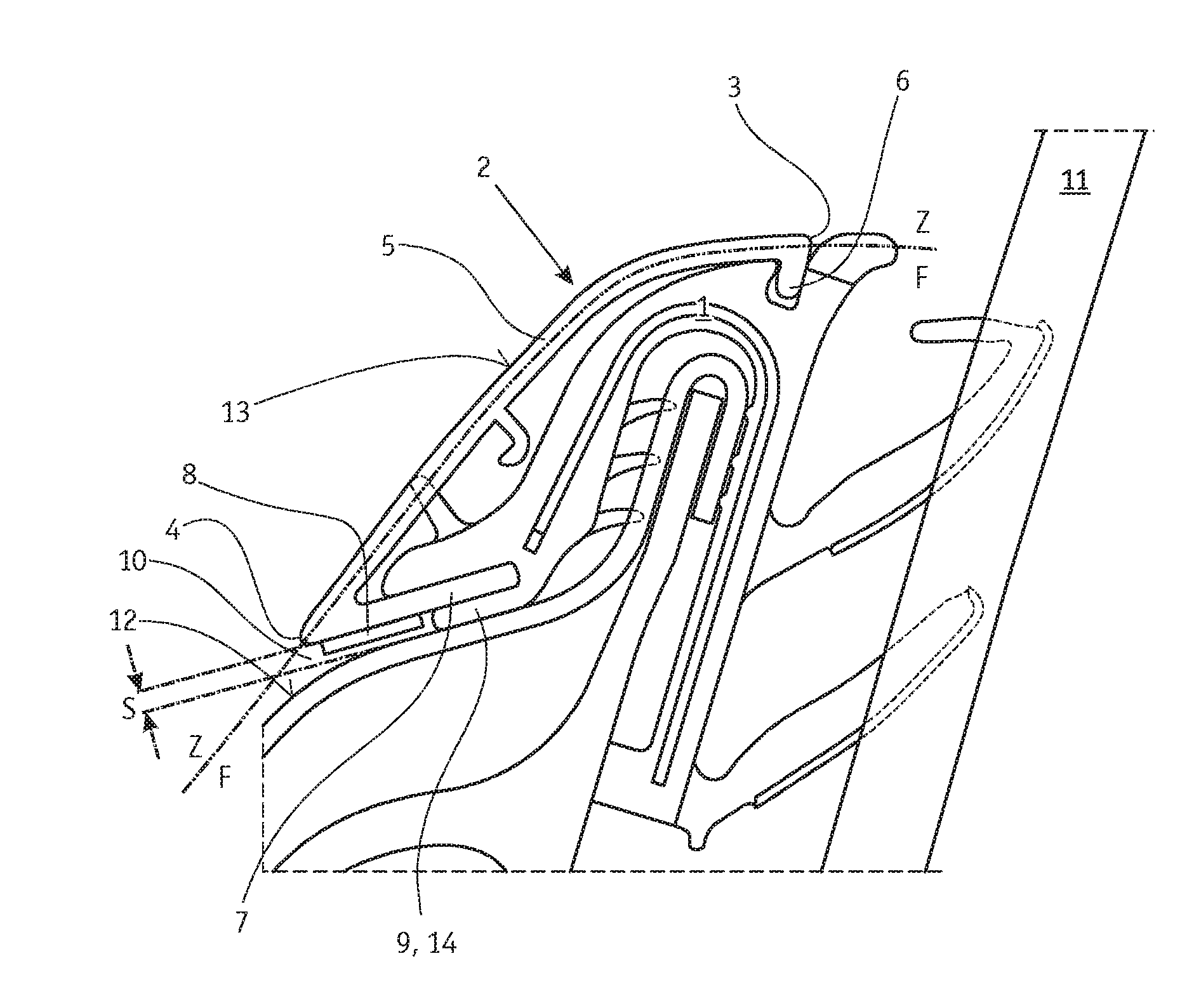
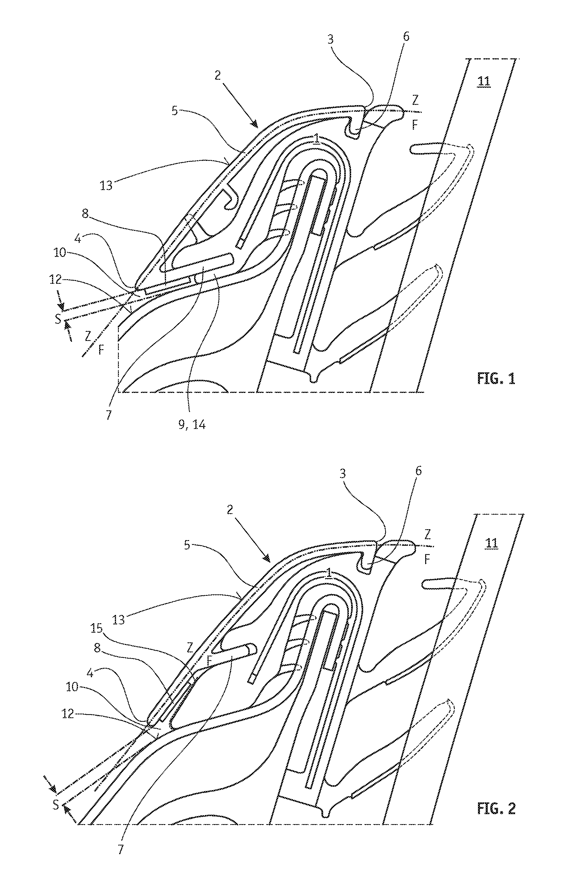
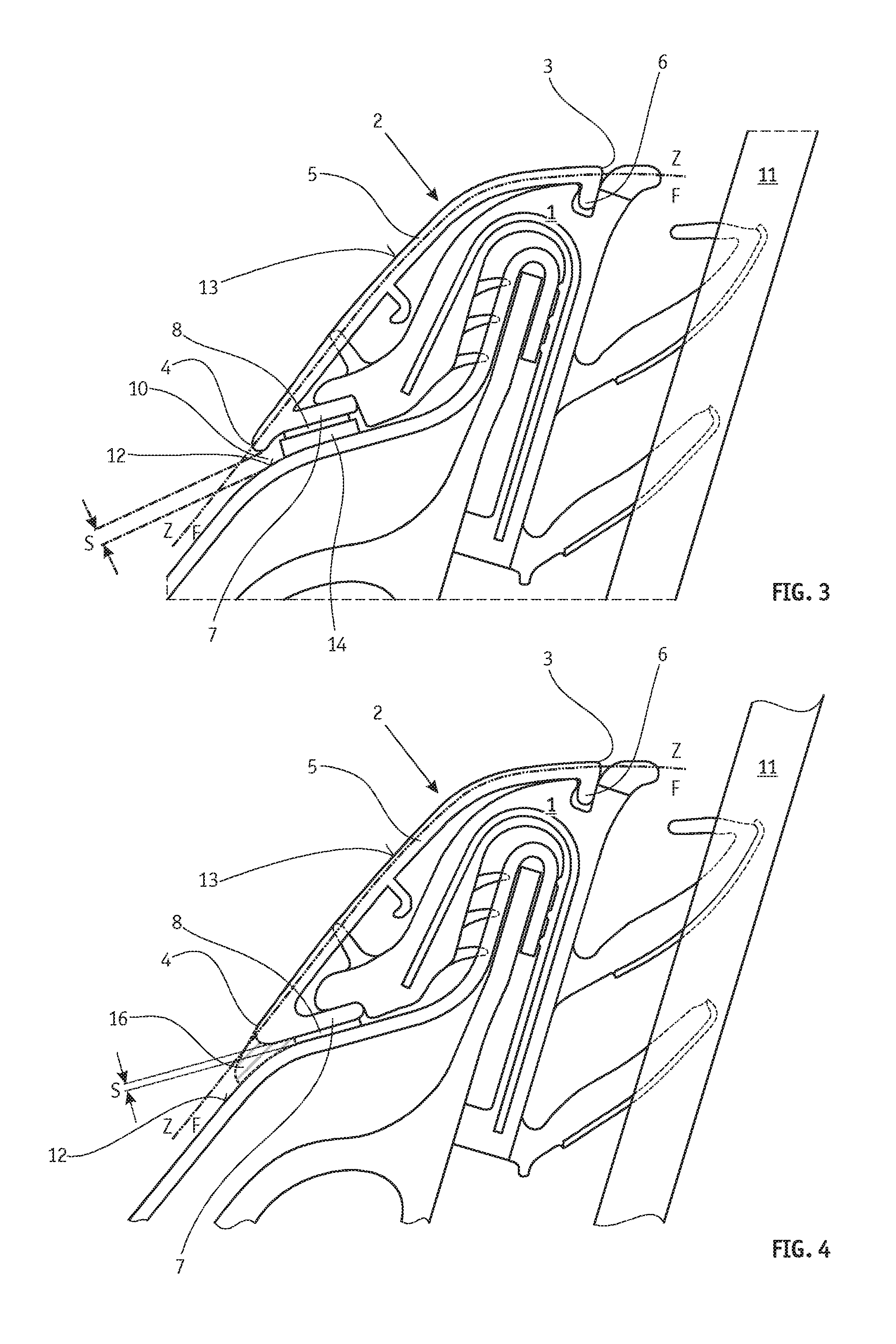
[0026]FIG. 1 illustrates a profiled strip 2, in the form of a window channel covering fitting, which is attached to a sealing strip 1. A further use would be, for example, a shoulder line trip strip or a cover strip for covering, for example, the A strip, B strip or C strip. The sealing strip 1 is fitted with its U-shaped section, reinforced by an inserted metal bar, onto a vehicle bodywork part of a motor vehicle and seals off the door well from the window pane 11. The profiled strip 2 is configured to cover this sealing strip 1 and to conceal it as a decorative part in a way which gives the most high-quality visual impression possible. For this purpose, the profiled strip 2 or the profiled strip cross section formed by the material of the profiled strip 2 has an arcuate main limb 5, the outwardly pointing surface of which forms the decorative surface 13 of the profiled strip 2 which is externally visible given correct mounting. The decorative surface 13 is bounded by an upper visi...


PUM

PropertyMeasurementUnit
thicknessaaaaaaaaaa
light gap widthaaaaaaaaaa

Abstract

An illuminated trim fitting for a motor vehicle, in particular a trim fitting as a cover fitting of a sealing strip for the window channel of a vehicle door, is intended to provide a high-quality illuminating effect accompanied at the same time by a simple structural design, low manufacturing costs and space-saving attachment. In addition, the trim fitting is to differ as little as possible externally from non-illuminated trim fittings. For this purpose there is provision that a light gap is formed between a profiled strip of the trim fitting and the adjacent vehicle outer skin, through which light gap the light emitted by a lighting structure provided on the rear of the trim fitting can exit to the outside.

Description

CROSS-REFERENCE TO RELATED APPLICATIONS[0001]This application claims priority to PCT application PCT / EP2015 / 055990 filed on Mar. 20, 2015, which claims priority to EP Application No. 14163945 filed on Apr. 8, 2014 and is herein incorporated by reference.FIELD OF THE INVENTION[0002]The invention relates to an illuminated trim fitting for a motor vehicle, in particular a trim fitting as a cover fitting of a sealing strip for the window channel of a vehicle door, and to a trim fitting arrangement on a vehicle, and to a motor vehicle having such a trim fitting arrangement, wherein the trim fitting has at least one lighting means and a profiled strip which, given correct final mounting on the vehicle, defines a decorative side which is directed away from the vehicle and which has an externally visible decorative surface of the profiled strip, and a functional side which is directed towards the vehicle and is not visible externally, wherein the at least one lighting means is arranged on s...

Claims


Application Information

Patent Timeline
Patent Type & Authority Applications(United States)
IPC IPC(8): B60Q1/00F21V7/22B60Q1/26F21S8/10B60J10/75B60J10/265
CPCB60Q1/0017B60J10/75B60J10/265F21V7/22B60Q1/2696F21S48/33B60Q1/268B60Q1/323B60R13/04F21V7/28F21S45/50
Inventor STEGEMANN, JANHUNDT, TORSTENROHNER, STEPHAN
Owner PLASMAN US HOLDCO LLC
Why Eureka
Try Eureka