LED module

Inactive Publication Date: 2017-02-09
PANASONIC INTELLECTUAL PROPERTY MANAGEMENT CO LTD
View PDF3 Cites 4 Cited by
  • Summary
  • Abstract
  • Description
  • Claims
  • Application Information

AI Technical Summary

Benefits of technology

[0013]With the present disclosure, it is possi

Problems solved by technology

With the development-type resist including an epoxy resin, however, the light reflectance of the resist decreases under a high-temperature or high-humidity environment, leading to a possible problem of deteriorating light-emitting properties of an LED module.
In this case, however, the resist is formed by applying a thermosetting resin to a resin substra

Method used


Image

  • LED module
  • LED module
  • LED module

Examples


embodiment

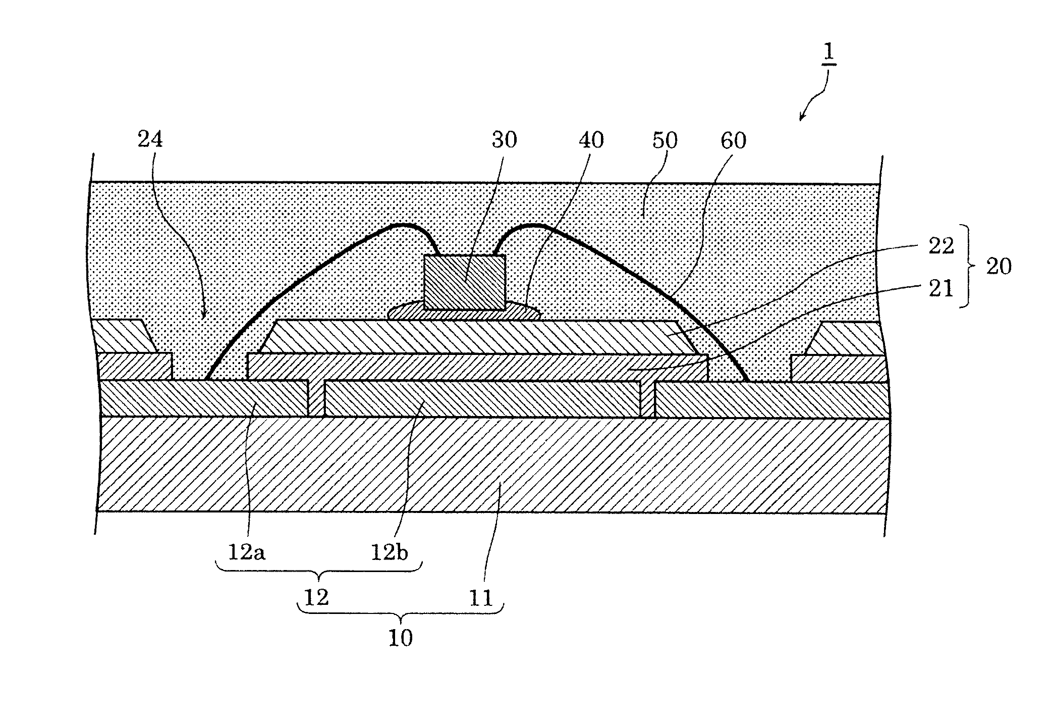
[0023]The following describes a configuration of LED module 1 according to an embodiment, with reference to FIG. 1 to FIG. 4.

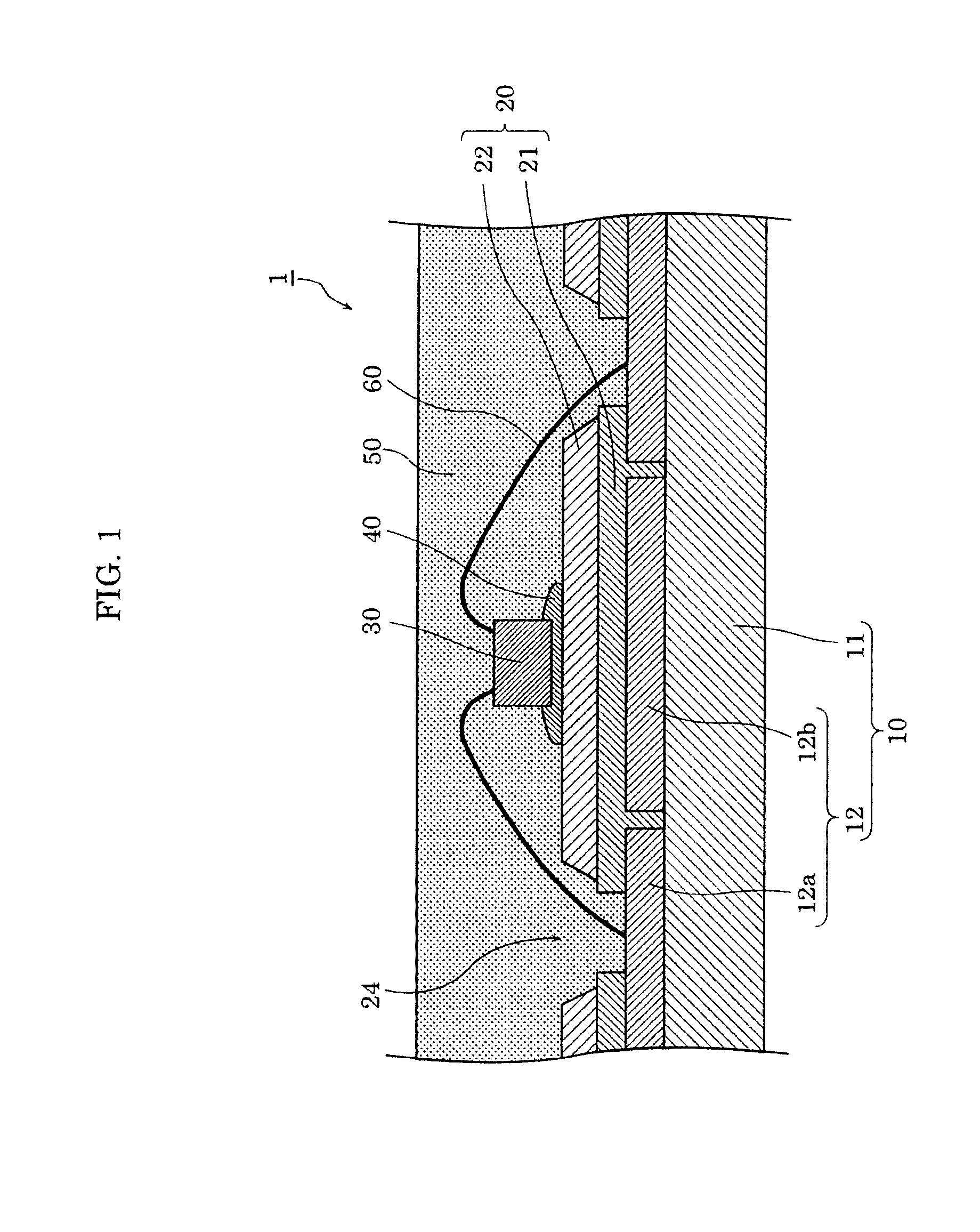
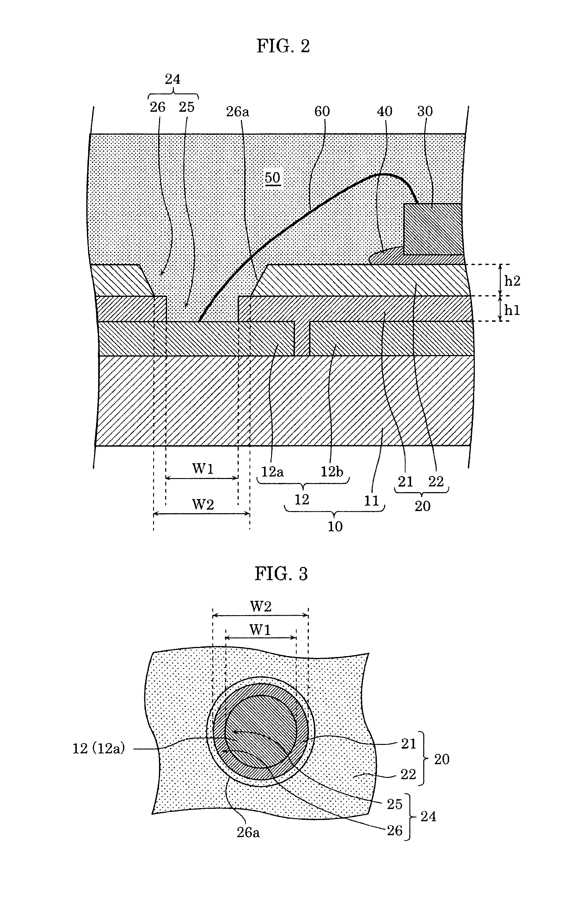
[0024]FIG. 1 is a partial cross-sectional view of LED module 1 according to the embodiment. FIG. 2 is a partially enlarged cross-sectional view of LED module 1 illustrated in FIG. 1. FIG. 3 is a schematic plan view illustrating opening 24 of resist 20 according to the embodiment. It should be noted that FIG. 3 illustrates an example of the shape of opening 24 when resist 20 is viewed from above (i.e., viewed from the side where LED element 30 is disposed on substrate 10), and each component is illustrated with dots, diagonal lines, etc., so as to facilitate distinguishing between the components. In addition, illustration of wire 60 is omitted in FIG. 3. FIG. 4 is a cross-sectional view illustrating a configuration example of an end portion of resist 20 according to the embodiment.

[0025]As illustrated in FIG. 1, LED module 1 includes substrate 10, resist 20, an...

modification 1

[0098]FIG. 5 is a partial cross-sectional view of LED module 1A according to Modification 1.

[0099]According to the above-described embodiment, resist 20 of LED module 1 includes first layer 21 and second layer 22 which are formed using different resist materials. In contrast, according to the present modifications resist 20A of LED module 1A includes first layer 21 and second layer 22A which are formed using the same resist material.

[0100]More specifically, first layer 21 and second layer 22A both include the development-type resist material according to the present modification. For example, first layer 21 includes a development-type resist material mainly made of an epoxy resin, and second layer 22A includes a development-type resist material mainly made of a fluorine resin.

[0101]In other words, in the present modification, second layer 22A that is the uppermost layer includes fluorine as a component, as with the above-described embodiment.

[0102]With this configuration, it is poss...


PUM


Abstract

A light emitting diode (LED) module which includes: a substrate; a resist including a plurality of layers above the substrate; and an LED element mounted above the substrate. The plurality of layers includes a second layer that is an uppermost layer and a first layer that is an underlying layer. The second layer that is the uppermost layer includes fluorine as a component.

Description

CROSS REFERENCE TO RELATED APPLICATION[0001]This application claims the benefit of priority of Japanese Patent Application Number 2015-153717 filed on Aug. 03, 2015, the entire content of which is hereby incorporated by reference.BACKGROUND[0002]1. Technical Field[0003]The present disclosure relates to a light emitting diode (LED) module including an LED.[0004]2. Description of the Related Art[0005]Semiconductor light-emitting elements such as LEDs are highly efficient and long-life elements, and thus widely used as light sources for various devices. An LED is used, for example, as an illumination light source in a lamp, a lighting device, etc., or as a backlight light source in a liquid-crystal display apparatus.[0006]The LEDs are generally unitized as an LED module and included in various devices. The LED module includes, for example, a substrate and at least one LED element mounted on the substrate.[0007]More specifically, an LED module is known which has a chip on board (COB) st...

Claims


Application Information

Patent Timeline
IPC IPC(8): H01L33/56H01L33/64H01L33/48H01L33/62
CPCH01L33/56H01L33/486H01L33/642H01L33/62H01L2924/181H01L33/44H01L33/501H01L2224/48091H01L2224/48228H01L2224/73265H01L2924/00014H01L2924/00012
Inventor TAGAMI, NAOKIABEFUJITANI, HISAKITAKEHARA, KOSUKEKURACHI, TOSHIAKI
Owner PANASONIC INTELLECTUAL PROPERTY MANAGEMENT CO LTD
Why Eureka
Try Eureka