Machine vision system

a machine vision and system technology, applied in the field of machine vision systems, can solve the problem that it is not inconceivable to provide a mixed system, and achieve the effects of enhancing the contrast of the image, enhancing and improving the accuracy and/or robustness of identification

Active Publication Date: 2017-02-16
ELEKTA AB
View PDF1 Cites 1 Cited by
  • Summary
  • Abstract
  • Description
  • Claims
  • Application Information

AI Technical Summary

Benefits of technology

[0013]The invention involves the use of a fluorescing marker in order to mark a leaf and / or the reference points within the field of view. The markers are illuminated with light tuned to cause the markers to fluoresce at a wavelength different to that of the illuminating light. The fluorescence is then detected by a camera. This method allows the image to be captured by the camera with increased contrast.
[0018]The fluorescent marker will usually emit light of a wavelength longer than the incident light, allowing suitable filters to be provided in order to distinguish the light emitted by the markers. A suitable material for use in the fluorescent markers is ruby. This can be in a spherical or a cylindrical shape, or another suitable shape. Several markers could of course be provided on a single leaf or leaves, ideally in different configurations so as to achieve greater accuracy and / or robustness of identification.
[0019]The present invention also provides a radiotherapeutic apparatus comprising a multi-leaf collimator as defined above, and a camera arranged to view the fluorescent markers. A source of illumination for the fluorescent markers will also be useful and is ideally monochromatic or nearly so. The camera can have a filter arranged to substantially prevent light of the wavelength emitted by the source of illumination from entering the camera, thereby improving the contrast of the image.
[0020]The radiotherapeutic apparatus can also comprise a source of illumination that is optically co-located with a radiation source, to allow the radiation field that is being emitted or will be emitted to be checked visually by an operator. The co-located source is preferably substantially monochromatic, emitting substantially no light at the wavelength of the fluorescent markers. A filter can then be placed over an output of the radiotherapeutic apparatus, for blocking light of the wavelength of the fluorescent markers and thereby enhancing the contrast of the image that is taken of the fluorescent markers.

Problems solved by technology

However, it is not inconceivable that a mixed system could be provided.

Method used


Image

  • Machine vision system
  • Machine vision system
  • Machine vision system

Examples


Embodiment Construction

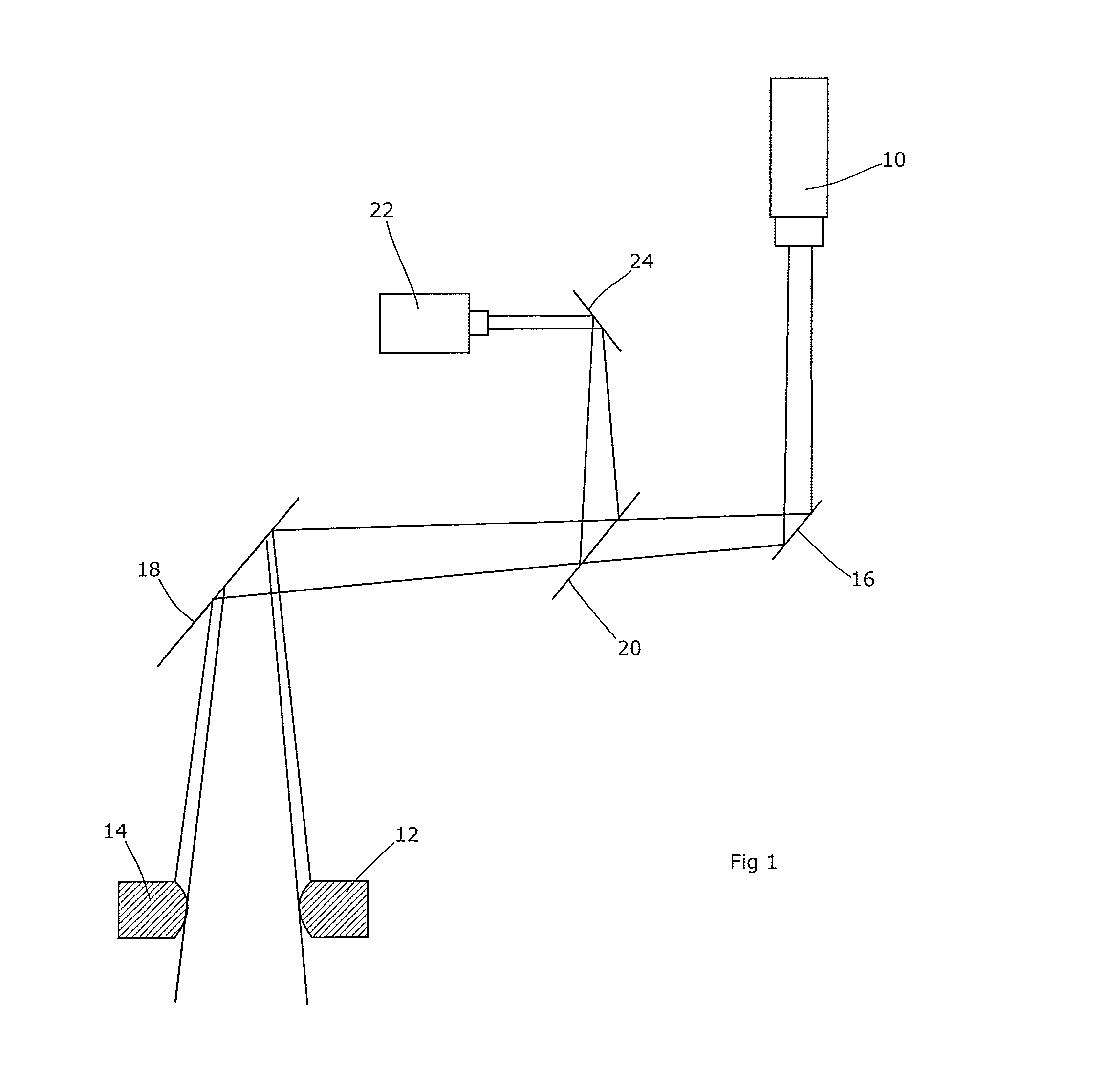
[0024]The present invention will be described in relation to sensing the position of a large number of MLC leaves within a radiotherapeutic apparatus. As noted above, these leaves operate within a harsh environment in terms of the ionising radiation that is deliberately created within the radiotherapy head and into which they must project in order to carry out their function. This harshness presents difficulties in the provision of a machine vision solution to leaf monitoring that is stable and reliable in the long term. The solution adopted in relation to the MLC leaves is of course applicable in other situations, particularly (but not exclusively) environments that are harsh or which present difficulties in distinguishing illuminated markers.

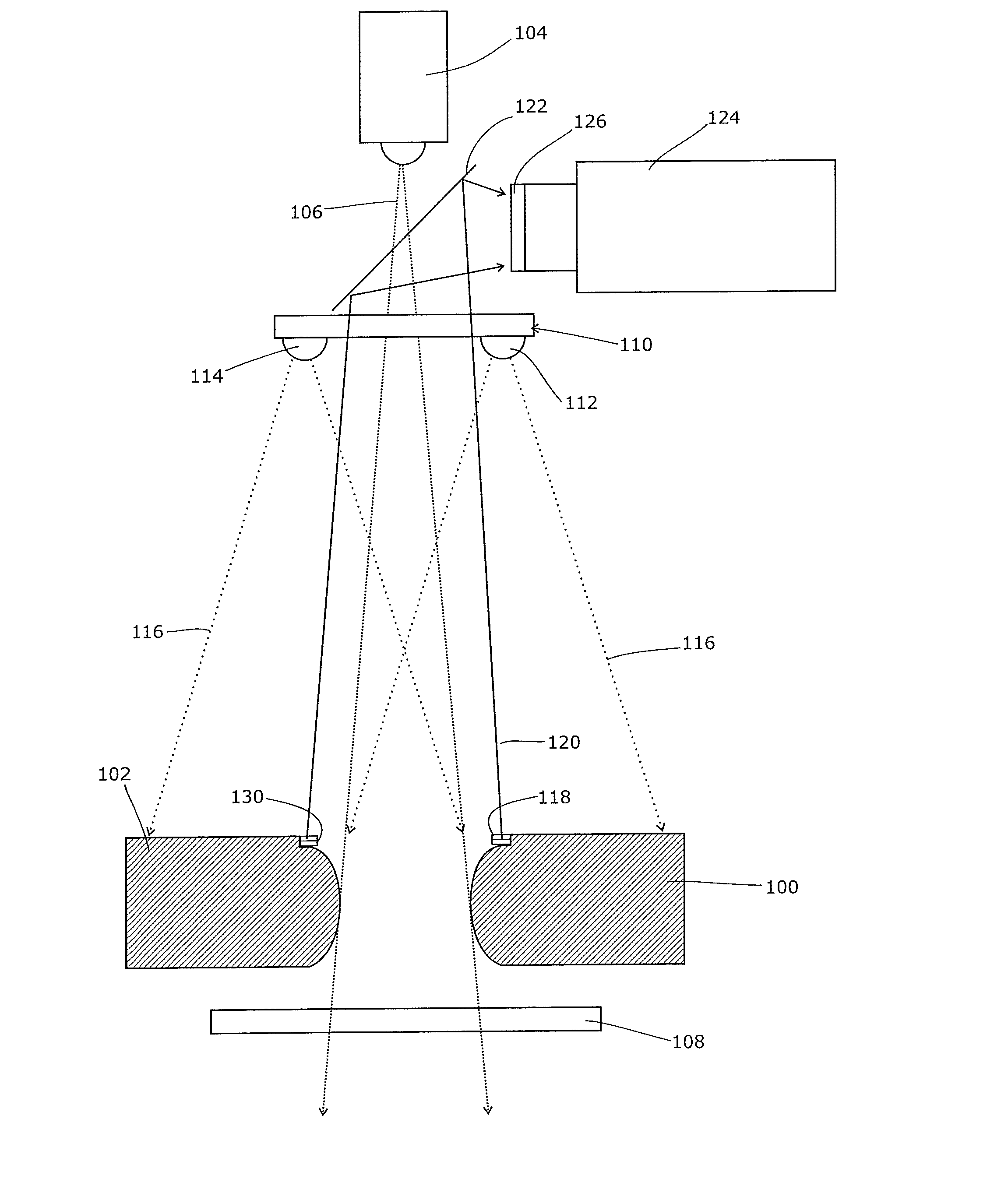
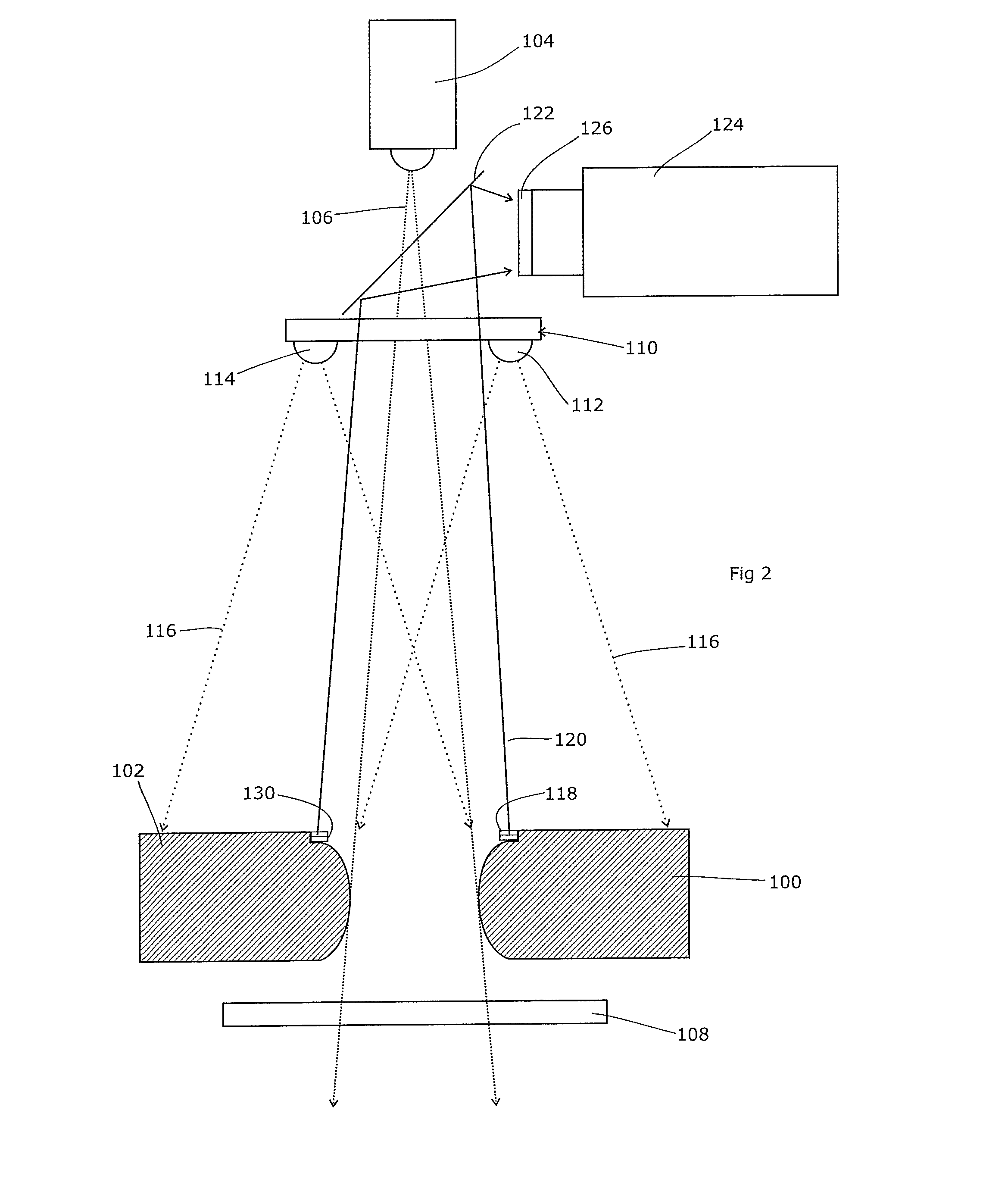
[0025]FIG. 2 shows an example of the present invention. For simplicity of illustration, the mylar mirror 18 of FIG. 1 has been omitted, so straight paths for some of the optical systems are shown. In practice, this mirror will of course be pro...


PUM


Abstract

A fluorescing marker is used in order to mark (for example) a leaf of a multi-leaf collimator and / or the reference points within the field of view. The markers are illuminated with light tuned to cause the markers to fluoresce at a wavelength different to that of the illuminating light. The fluorescence is then detected by a camera. This method allows the image to be captured by the camera with increased contrast. Accordingly, the present invention provides a multi-leaf collimator for a radiotherapeutic apparatus, comprising at least one leaf having a fluorescent marker. The fluorescent marker will usually emit light of a wavelength longer than the incident light, allowing suitable filters to be provided in order to distinguish the light emitted by the markers. A suitable material for use in the fluorescent markers is ruby. The present invention also provides a radiotherapeutic apparatus comprising a multi-leaf collimator as defined above, and a camera arranged to view the fluorescent markers. A source of illumination for the fluorescent markers is ideally monochromatic, or nearly so. The camera can have a filter arranged to substantially prevent light of the wavelength emitted by the source of illumination from entering the camera, thereby improving the contrast of the image. The radiotherapeutic apparatus can also comprise a source of illumination that is optically co-located with a radiation source, to allow the radiation field that will be emitted to be checked visually by an operator. The co-located source is preferably substantially monochromatic, emitting substantially no light at the wavelength of the fluorescent markers. A filter can then be placed over an output of the radiotherapeutic apparatus, for blocking light of the wavelength of the fluorescent markers and thereby enhancing the contrast of the image that is taken of the fluorescent markers.

Description

CROSS-REFERENCE TO RELATED APPLICATION[0001]The present application is a continuation of and claims priority of U.S. patent application Ser. No. 12 / 362,664, filed Jan. 30, 2009, which claims priority of British patent application Serial No. 0801895.4, filed Feb. 1, 2008, the contents of which are hereby incorporated by reference in their entirety.FIELD OF THE INVENTION[0002]The present invention relates to a machine vision system. It provides a solution to problems that arise in machine vision applications in hostile or otherwise difficult environments, such as the interior of a radiotherapeutic apparatus.BACKGROUND ART[0003]Radiotherapeutic apparatus involves the production of a beam of ionising radiation, usually x-rays or a beam of electrons or other sub-atomic particles. This is directed towards a cancerous region of the patient, and adversely affects the tumour cells causing an alleviation of the patient's symptoms. Generally, it is preferred to delimit the radiation beam so th...

Claims


Application Information

Patent Timeline
Patent Type & Authority Applications(United States)
IPC IPC(8): A61N5/10H04N5/225G21K1/04G06T7/00
CPCA61N5/1049A61N5/1045G06T7/0012H04N5/2256G06T2207/10064G21K1/046A61B2090/3941A61N2005/1059G06T2207/30204G21K1/04A61N5/1042A61N5/1048G01B11/14G01V8/12G01V15/00G21K1/02H04N23/56
Inventor AWAN, SHAKIL AHMEDSMITH, ADRIAN MAXWELL
Owner ELEKTA AB
Why Eureka
Try Eureka