Method and device for replacing the printing roller of a printing unit of a printing machine

a printing unit and printing roller technology, applied in the direction of printing, rotary presses, other printing apparatus, etc., can solve the problems of large amount of wasted material, large amount of waste of materials, and large device construction complexity and bulky, and achieve the effect of increasing the efficiency and productivity of printing processes

Active Publication Date: 2017-02-16
BOBST FIRENZE
View PDF6 Cites 11 Cited by
  • Summary
  • Abstract
  • Description
  • Claims
  • Application Information

AI Technical Summary

Benefits of technology

[0005]The object of the present invention is to provide a device for replacing the printing rollers of a printing unit, in particular for in-line rotary flex

Problems solved by technology

Moreover, the change-over between two different printing jobs generally results in a huge amount of wasted material.
This device is constructionally complex a

Method used


Image

  • Method and device for replacing the printing roller of a printing unit of a printing machine
  • Method and device for replacing the printing roller of a printing unit of a printing machine
  • Method and device for replacing the printing roller of a printing unit of a printing machine

Examples


Embodiment Construction

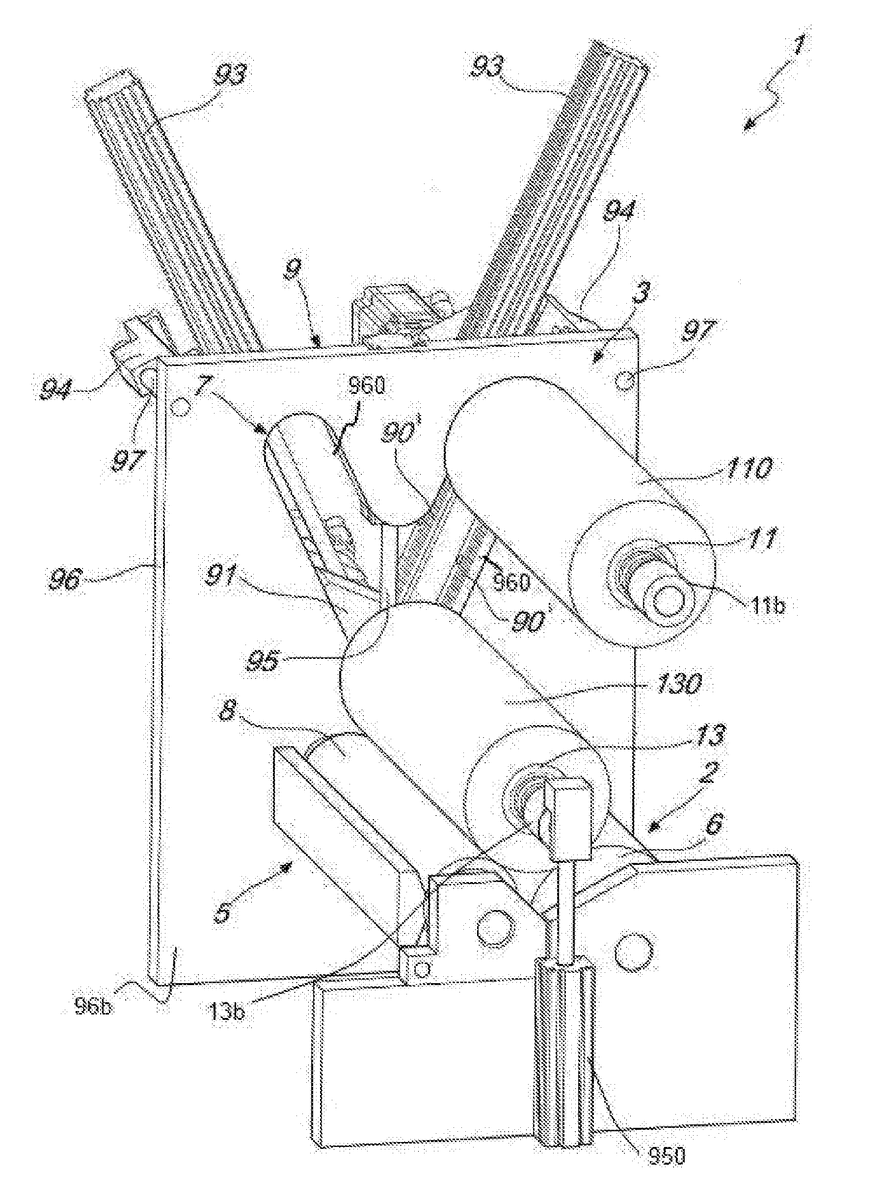
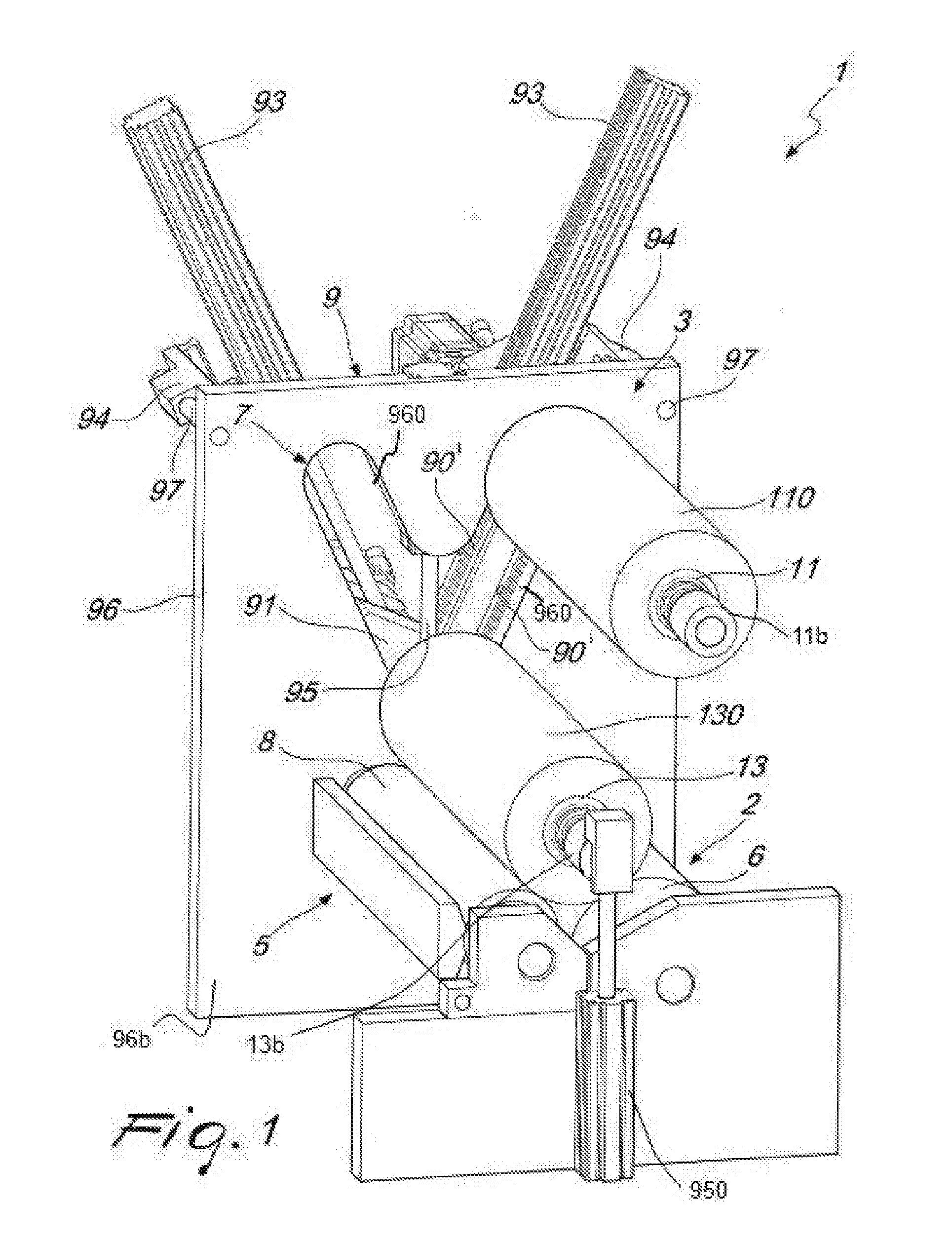
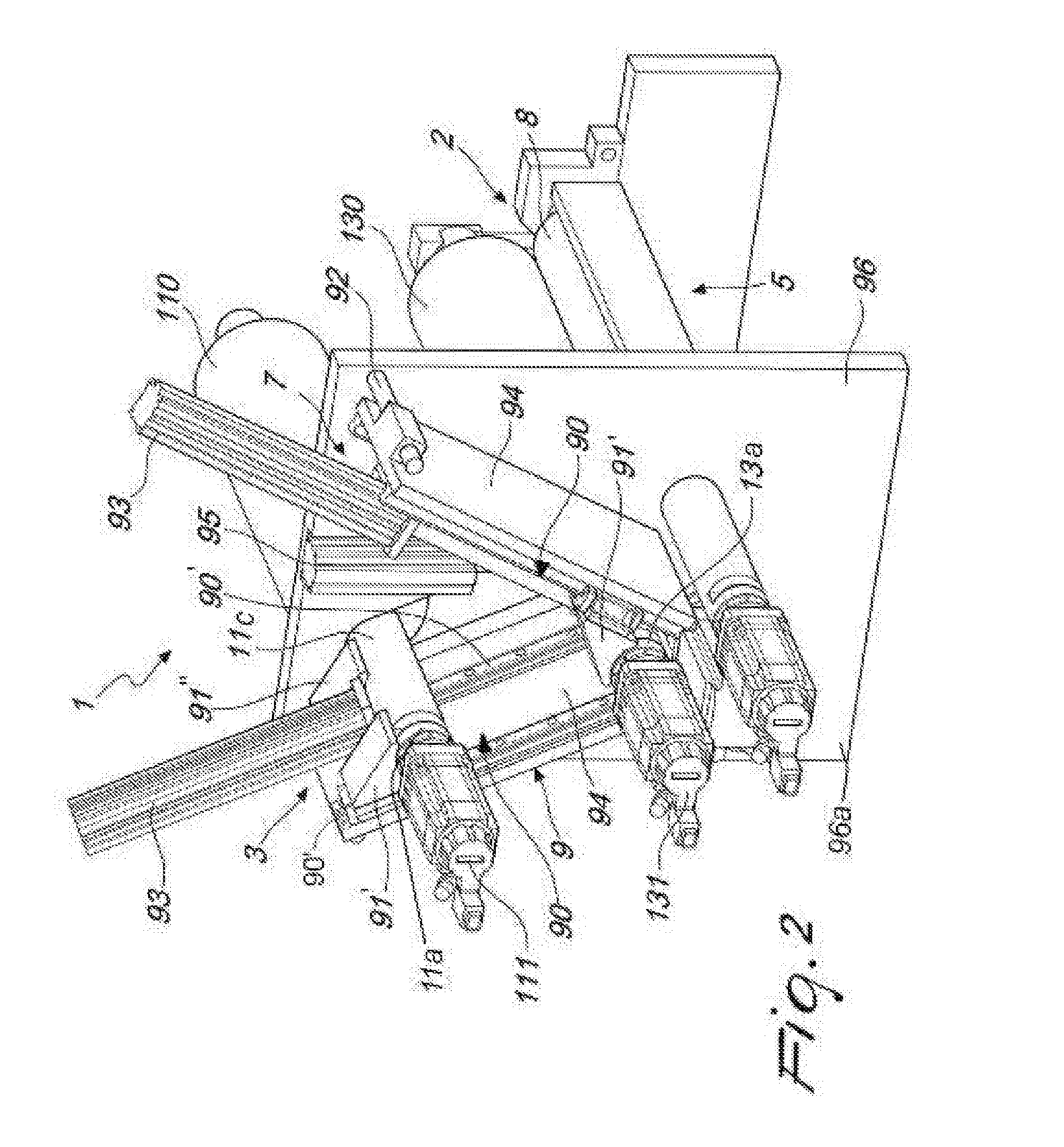
[0016]With reference to the aforementioned figures, the device for replacing the printing roller of a printing unit is denoted overall by the reference number 1, while the printing unit is denoted overall by the reference number 2 and comprises at least one anilox roll 8 and one counter-roll 6.

[0017]According to the invention, the device 1 comprises a work station 5 for a first working printing roller 130 associated with a first support spindle 13, a holding station 3, 7 for a second holding printing roller 110 associated with a second support spindle 11, a removal station 7, 3 for removing a printing roller 110, 130 to from a support spindle 11, 13, and displacement means 9 for displacing the first support spindle 13 from the work station 5 to the removal station 7, 3 and for displacing the second support spindle 11 from the holding station 3, 7 to the work station 5.

[0018]The work station is arranged in a substantially intermediate position between the removal station 7, 3 and the...


PUM


Abstract

The present invention relates to a device for replacing the printing roller in a printing unit, in particular for in line rotary flexographic machines.

Description

TECHNICAL FIELD OF THE INVENTION[0001]The present invention relates to a device for replacing the printing roller in a printing unit, in particular for in-line rotary flexographic machines.BACKGROUND OF THE INVENTION[0002]At present, in the printing sector, and in particular in the sector of printing labels and flexible wrappings, there exists a very urgent need to increase the general efficiency of the printing processes, on the one hand reducing the printing time and on the other hand limiting the wastage of material, such as the printing medium.[0003]In particular, the step of changing the printing rollers is one of the most critical steps in the entire printing process since the so-called “job change-over” times constitute downtime, during which the printing process is substantially interrupted. Moreover, the change-over between two different printing jobs generally results in a huge amount of wasted material.[0004]Some solutions for automatically changing the printing rollers a...

Claims


Application Information

Patent Timeline
IPC IPC(8): B41F27/06
CPCB41F27/06B41F5/24B41F13/20B41F13/30B41F13/40B41F27/10B41F27/105B41P2217/15B41P2227/21
Inventor BASTICI, MASSIMOD'ANNUNZIO, FEDERICOMACCALLI, GIACOMOMACCALLI, MAURO
Owner BOBST FIRENZE
Why Eureka
Try Eureka