
Door handle assembly for a motor vehicle

a technology for motor vehicles and handle assemblies, which is applied in the direction of mechanical equipment, carpet fasteners, and lock applications, etc., can solve the problems of significant risks to a passenger in the motor vehicle, unintentional opening of the door of the motor vehicle, and unintended movement of the handle, so as to achieve simple and cost-effective

Inactive Publication Date: 2017-02-16
HUF HULSBECK & FURST GMBH & CO KG
View PDF2 Cites 4 Cited by
  • Summary
  • Abstract
  • Description
  • Claims
  • Application Information

AI Technical Summary

Benefits of technology

The invention provides a door handle assembly for a motor vehicle that is simple and cost-effective to assemble. The locking device in the assembly is designed to securely block the operating handle even in the event of a crash. The locking device has the ability to move in more than one direction, increasing its field of application. The coupling device and locking device have a predefined interaction that allows for a simple and cost-effective design. A mechanical return element is provided to force the locking device back into its normal operating position, allowing for continued use and actuation of the operating handle after the effects of acceleration forces. The mechanical return element retains the locking device in the normal operating position until an acceleration force reaches at least a predetermined threshold, preventing unintended activation of the locking device.

Problems solved by technology

Door handle assemblies of this type, having a locking device serving as a mass locking device, are intended to prevent the acceleration force occurring in an accident leading to an actuation of the operating handle, or door handle, respectively, and resulting in an unintentional opening of the door of the motor vehicle, which is accompanied by significant risks to a passenger in the motor vehicle.
In the case of an accident, the acceleration forces act, in unfavorable circumstances, in the manner of an actuation of the handle component by a user, because the handle can be accelerated in the opening direction due to inertia.
In the case of an accident, forces are exerted on a locking member, and an unintended movement of the handle, likewise caused by the forces acting thereon, is blocked.
With door handle assemblies known from the prior art, having a mass locking device, or a locking device, respectively, that does not lock in place when activated, but rather returns, or swings, respectively, to its normal operating position, there is the disadvantage that, with the effects of acceleration forces, the locking device can move, or swing, back and forth, such that the locking device can become located in a position during its swinging, in which the pivot arm, or the operating handle, respectively, is not blocked, despite the crash.
This is because the known locking devices are only active in a relatively small operating displacement range that blocks an actuation of the pivot arm, or operating handle, respectively, such that, either with strong and pronounced oscillations, or with oscillations occurring over a long period of time as a result of the effects of acceleration forces, there is the danger that, with locking devices swinging back and forth, the operating displacement range is not sufficient for reliably preventing a blocking of the operating handle, or pivot arm, respectively.

Method used


Image

  • Door handle assembly for a motor vehicle
  • Door handle assembly for a motor vehicle
  • Door handle assembly for a motor vehicle

Examples


first embodiment

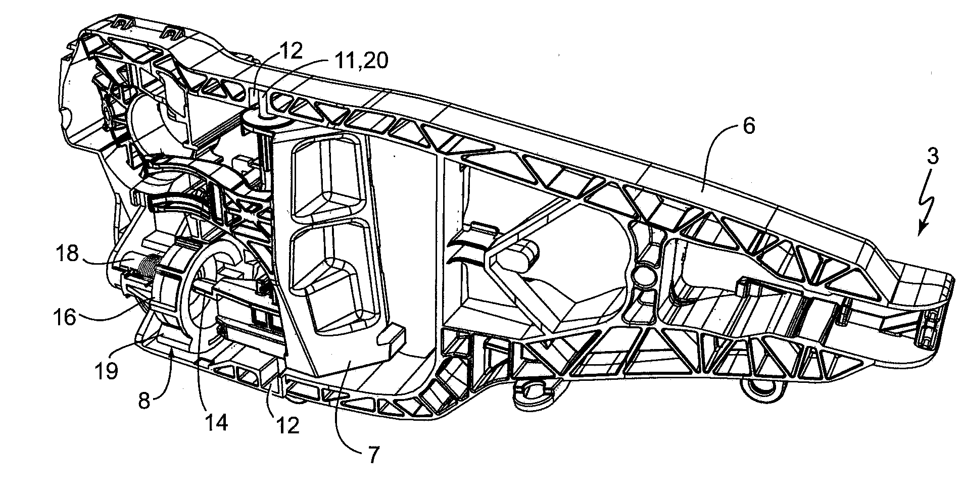
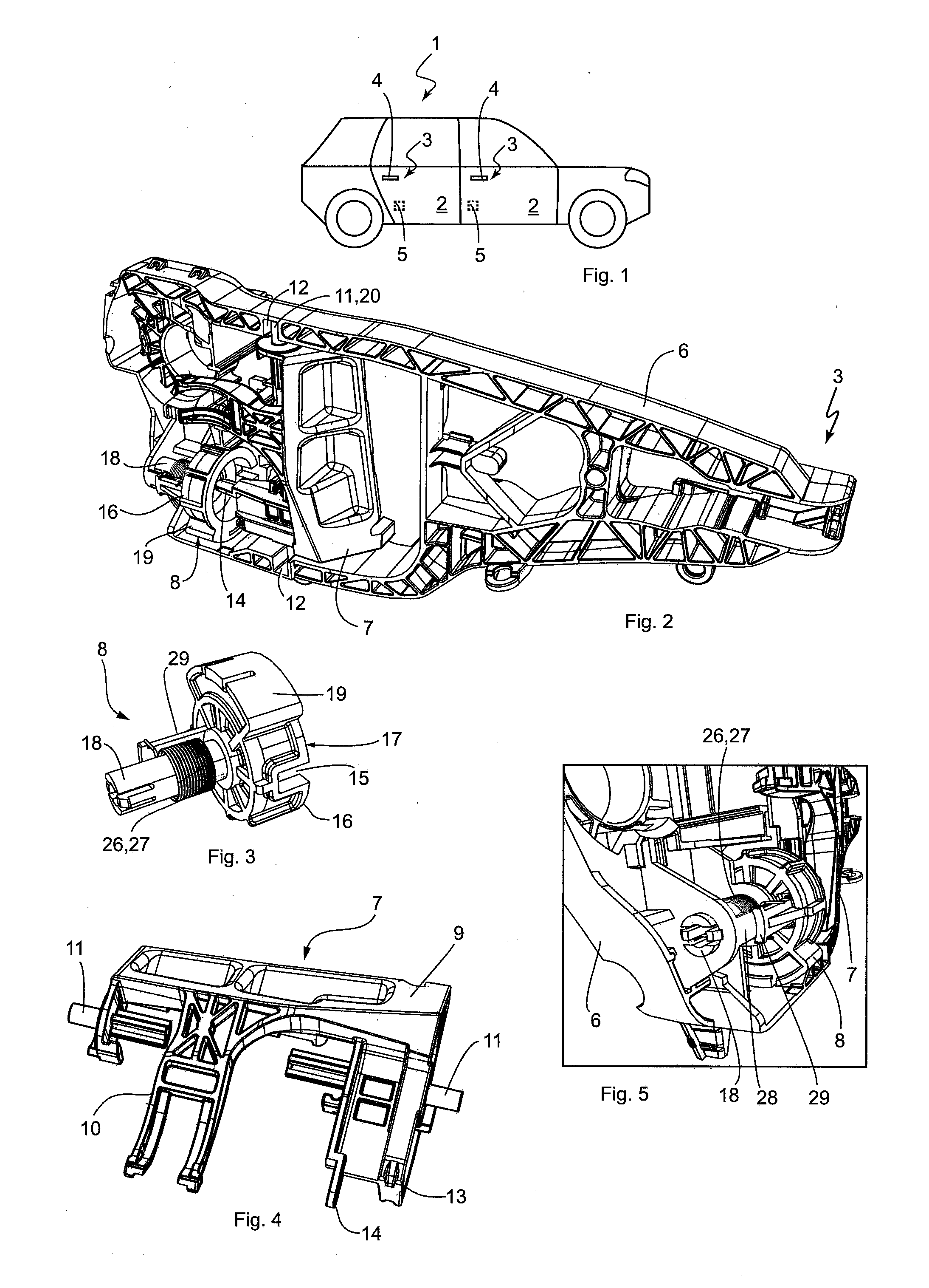
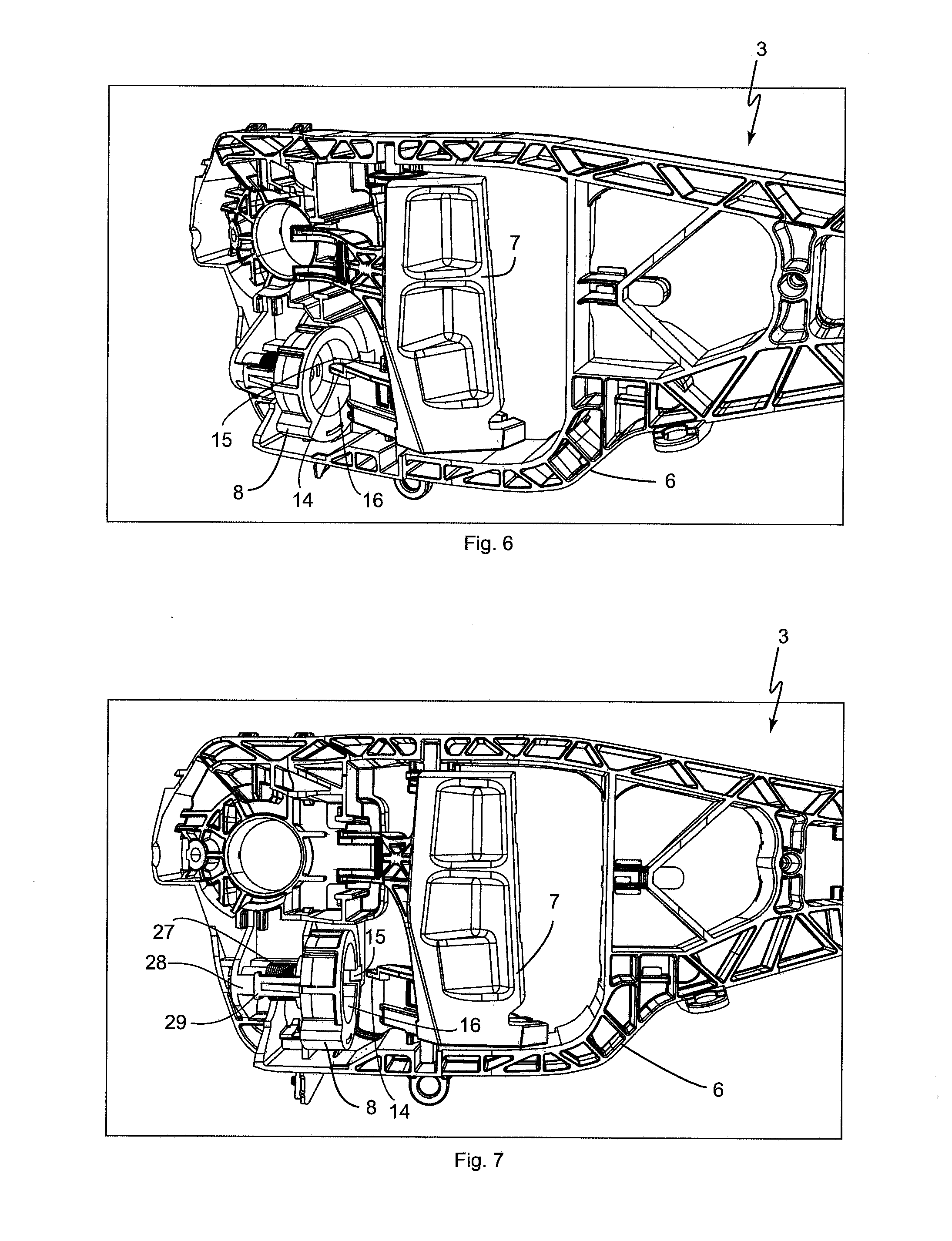
[0052]In the door handle assembly 3, the locking device 8 is designed in sections as a hollow cylinder 16, as is shown in FIGS. 2 and 6-9. The movement cavity 15 is formed in the shell of the hollow cylinder 16, running in the longitudinal direction, and represents a type of incision in the open front end 17 of the hollow cylinder 16 (see FIG. 3). In other words, the movement cavity 15 of the locking device 8, starting at the open front end 17 of the hollow cylinder 16, is formed running in the longitudinal direction thereof.

[0053]A state of the door handle assembly 3 is shown in FIG. 2, in which the locking device 8 is in its normal operating position and is thus not activated. Furthermore, in this state, the coupling device 7 is disposed in the rest position, because the operating handle is not actuated. In the normal operating position of the locking device 8, when the operating handle 4 is not actuated, the movement projection 14 extends into the open front end 17 of the hollow ...

second embodiment

[0058]With the door handle assembly 3′, the locking device 8′ is designed in sections as a disk element 23, as is shown, for example, in FIGS. 11 and 12. The movement cavity 15′ is formed on one of the two lateral surfaces of the disk element 23 as a guide channel 24, open on one side (see FIGS. 12 and 18, by way of example), for guiding the movement projection 14′ when the locking device 8′ is in its normal operating position. The guide channel 24 extends on the lateral surface of the disk element 23, offset to its center.

[0059]FIGS. 10 and 15 each show a state of the door handle assembly 3′, in which the locking device 8′ is disposed in its normal operating position, and the coupling device 7′ is in the rest position, due to the operating handle 4 not being actuated. The movement projection 14′ of the locking device 8′ is disposed in the normal operating position, outside of the guide channel 24 when the operating handle 4 is not actuated. In the state shown in FIGS. 10 and 15, th...


PUM


Abstract

A door handle assembly for a motor vehicle includes an operating handle moveably supported on a handle mounting, a mechanical coupling device and a locking device. An acceleration force can move the locking device from a normal operating position, in which an actuation of the operating handle is possible, in a first blocking direction, in which an actuation of the closing assembly via the operating handle and / or the coupling device, is blocked. The locking device also blocks the door handle assembly when long lasting or strongly pronounced oscillations occur as a result of a crash. In that event, the locking device can move from the normal operating position in a second blocking direction, in which an actuation of the closing assembly via the operating handle and / or the coupling device is blocked, wherein the second blocking direction is oriented opposite the first blocking direction.

Description

BACKGROUND[0001]The instant application is a divisional application of U.S. Ser. No. 14 / 295,405 which was filed on Jun. 4, 2014 and is still pending.[0002]The invention relates to a door handle assembly for a motor vehicle, having a frame-like handle mounting, an operating handle that is moveably supported on the handle mounting for opening a door or hatch of the motor vehicle by user, a mechanical coupling device, by means of which a movement of the operating handle can be transferred to a vehicle-side closing assembly, and a locking device serving as a mass locking device, which is moveably retained on the handle mounting and is designed such that, with the effect of an acceleration force, it can be moved from a normal operating position, in which an actuation of the operating handle is possible, in a first blocking direction, in which an actuation of the locking assembly by means of the operating handle and / or the coupling device is blocked.[0003]Door handle assemblies of this ty...

Claims


Application Information

Patent Timeline
Patent Type & Authority Applications(United States)
IPC IPC(8): E05B77/06E05B85/10
CPCE05B85/10E05B77/06Y10S292/22Y10T292/57E05B77/02
Inventor BECK, ANDREASLENNHOFF, RALFCHRISTENSEN, MARIO
Owner HUF HULSBECK & FURST GMBH & CO KG
Learn More